Bellpush

Bellpush For Sale

I’ve finished the bellpush and put it up for sale on eBay.

All the previous posts about the project are here.

Specifications

  • 2″ (51mm) wide, 2 ¼” (57mm) tall, 1 3/8″ (35mm) deep.
  • Hand cut stainless steel front plate.
  • Light green glow-in-the-dark vinyl membrane behind the fretwork.
  • Stainless steel button and front plate screws.
  • Varnished oak backing box.
  • Brass electrical screw terminals.
  • Heavy duty sterling silver contacts, suitable for electromagnetic bells.

finished_bell_push_1

finished_bell_push_2

Bellpush Final Details

The bellpush is almost finished. It just needs another two or three coats of exterior varnish, then I’ll put it up for sale (haven’t decided how yet – probably an eBay auction). Here are pictures of a few of the final details.

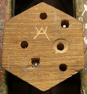
Deeply countersunk holes for three mounting screws (I thought two might be a little wobbly if the wall/door isn’t completely flat, particularly as there wasn’t room to space the screws evenly):

bellpush_details1

My maker’s mark carved on the back. This is a different thing to the Holden Concertinas logo (which isn’t on the bell push because I haven’t designed it yet). The HC logo will be the company brand and will be externally visible; my maker’s mark is my personal signature and is usually hidden away somewhere (I put it on most other things I make too).

bellpush_details2

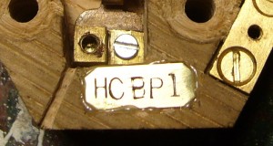
A brass serial number plate (visible when you remove the top plate), rather crudely stamped with a worn set of letter punches. The letters stand for “Holden Concertinas Bell Push 1”. Also seen in this picture is a little drain slot so any rainwater that leaks into the switch recess can run out of the bottom.

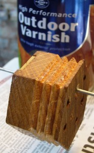
First coat of exterior clear varnish (thinned down so it soaks into the grain), after sanding the bellows valleys because the bottoms of the trenches were a bit fluffy. The grain of the plain oak looks really pretty. I debated with myself for quite a while over whether to stain it darker to look more like a vintage rosewood concertina. In the end, after staining and varnishing a test piece, I decided against it because it looked a bit fake and the end grain stained much darker than the side grain.

bellpush_details4

Fiddly Fretwork

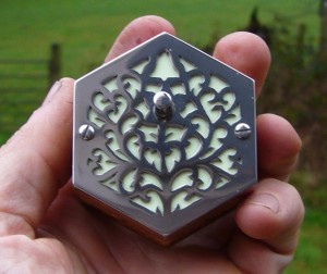
Because I made the bellpush fretwork before I started this blog, I thought I would take a step back and write a bit about how I did it. Here’s a picture of the finished item (remember it’s only 50mm wide):
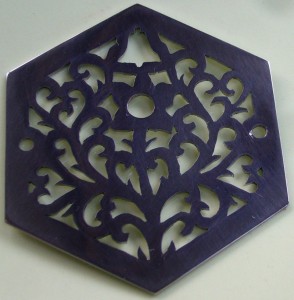
Bell Push Top

What I didn’t do was to design it 1:1 with paper and a pencil. Given my limited artistic ability and the level of fine detail involved, using computer aided design software saved me a lot of time and almost certainly led to a better end result. I could zoom in and out, automatically turn wonky hand-drawn curves into nice smooth ones, repeatedly draw and erase (without leaving smudgy marks each time), undo, redo, tweak, retweak, and basically fiddle with the design for hours on end until I felt it was good enough to hit ‘print’. That’s my little secret: I’m not very good at freehand drawing (I wish I was), but if you’re patient enough CAD lets you keep on making hundreds of tiny incremental improvements until you finish up with something that looks pretty good. In theory also I could go from a vector drawing to a control program for a CNC tool like a laser cutter, which is something I want to try in the future, though this project was about learning to cut an end by hand.

The software I used is an open source vector drawing program called Inkscape. I’m using a snapshot of the current development version for two reasons: it has a couple of whizzy new features that make it easier to do this kind of design, and it finally runs natively on Mac OS X rather than via the rather clunky X11 interface. The two new features are both path effects: spiro spline and power stroke (stupid name). Spiro spline basically makes it easy to draw really smooth curves. Power stroke lets you draw variable width lines (you can later convert a power stroke into an outline path – i.e. two curves that define the edges of the power stroke line; unfortunately that’s a one-way conversion). Rather than me spend a few hundred words attempting to explain more clearly why the combination of these two features is really useful for drawing the scrolly shapes you find in a Victorian-style concertina end, take a look at this video. (Incidentally, he would have been better off using the Path->Union command at the end to combine multiple powerstrokes into a single path.)

It took me three attempts to come up with a design I was happy with. Here are the three versions side by side:


top1 top2 top3

I spent a lot of time studying pictures of vintage concertina ends between attempts 2 and 3: I could tell my version looked wrong but it took a lot of analysis before I figured out exactly why and how to fix it. Something you might notice if you look closely is that in the first two the right and left hand sides are almost exact mirror images of each other. In the third one there are many very small differences between the two sides – this asymmetry, I found, makes the design look far more organic.

If you carefully compare the final design to the photo above, you’ll spot where I made a mistake with the saw in one place. I carefully tweaked the design to work around the mistake and it almost looks like I did it on purpose now!
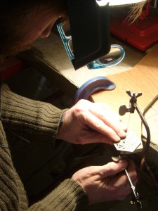
Hand piercing a stainless steel concertina-style bell push

I cut the end by hand with a jeweller’s piercing saw, following a paper template glued to a piece of 1mm stainless steel. I used stainless because the bell push needs to be weather resistant – metal concertina ends are more commonly made of nickel-silver AKA German silver, which is actually a type of brass and is much easier to cut, though it would quickly tarnish outdoors. The biggest mistake I made was putting wax polish on the paper – I thought it would lubricate the saw blade and save me having to keep manually waxing the blade. Bad idea. The sawing generated a very fine black dust which stuck to the waxy paper and smudged it so badly that eventually I couldn’t see the lines clearly (hence the mistake mentioned above, caused by carrying on cutting where I thought there was supposed to be a line). After that mistake I printed out and glued a new template on top of the smudged one – very tricky to get the two perfectly registered – but then I had lots of problems with the bottom, waxy layer coming unstuck from the metal when I was cutting the points of the scrolls, hence why many of the points are slightly misshapen.
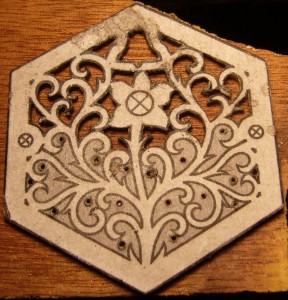
halfway

Another problem I ran into was blunting and breaking 1mm drill bits because I centre-punched where I wanted the holes to go, which work-hardened the stainless enough to cause my HSS drill bits to rub and go blunt instead of cutting. I switched to solid carbide bits (actually re-sharpened PCB drilling bits from eBay, which are good and surprisingly cheap). They cut through the work-hardened stainless OK, but I broke several of them because they tend to snatch as they break through the back of the work. Carbide is so brittle and delicate that the bits just instantly snap when that happens. In hindsight a better solution might be: a. mark the drill points using a centre drill or a tri-cornered centre punch and a very light tap to avoid work hardening the material, b. drill on top of a sacrificial piece of brass or aluminium to reduce the likelihood of snatching on break-through. I could also try using good quality cobalt bits instead of carbide.

The final problem I encountered was that of blunting and breaking jeweller’s saw blades. I must have gone through two or three dozen of them. I’m talking about very fine blades here – the teeth are so small that you can barely see them with the naked eye. They need to be small so you can cut the tiny details and tight curves inside the piercings. I started out using a highly-regarded brand that I have had success with in the past when cutting silver and brass, but they turned out to be not hard enough for stainless – they tend to go dull in one or two strokes. I found another brand that stays usably sharp for a bit longer (perhaps two piercings), but it’s still extremely easy to snag the blade in the cut and snap them because they are so tiny and delicate. It’s also very hard to follow a line closely with a dull blade because it tends to want to drift off in one direction or the other depending on which side happens to be sharper. One trick I might try in future is cutting out the bulk of each piercing out with a thicker, more robust blade, then going back later and doing the inner points and other details with a fine blade.
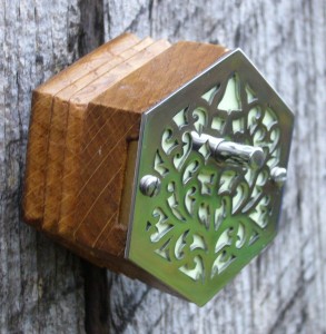
Swanky Switch

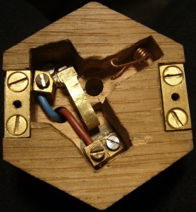
I’ve spent what seems like an inordinate amount of time getting the bellpush switch right. This photo shows my first attempt:

switch1

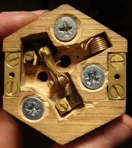
The long contact strip is made from a roughly T shaped strip of 0.7mm brass. It’s bent into a zig-zag at one end to make it more flexible (I also had to file it narrower for the same reason). One of the problems I ran into was I initially didn’t recess the contacts deep enough to ensure the terminal screws can’t press against the underside of the top. The top of the flexible strip is slightly curved so that when the lip of the button pushes down on it, it flexes a little and ‘wipes’ the contacts against each other to (in theory) break through any oxide film that may have developed since the last time it was used. The contacts are made of short sections of flattened 4mm diameter sterling silver rod (for good corrosion resistance), silver-soldered onto the brass parts. The screw terminals are salvaged from a UK 13A mains plug, filed a bit narrower due to the limited space available. I did all the soldering with the Eclipse spirit blowpipe described in an earlier article. They are held down by M2.5 stainless steel machine screws, mated to square S.S. nuts morticed into the back of the box.

When I got to this stage I thought the switch was done. The button action felt nice and the contacts closed when I pressed it. Unfortunately there was a problem, as I discovered when I proudly showed it off to my friend Juliet. She pressed it normally a couple of times and it worked fine, then she tried pressing it really gently. It didn’t work. She tried the same thing a few more times with intermittent results and proclaimed it faulty.

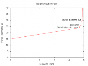
It was a user interface problem: press the button down firmly all the way to the bottom and it worked fine. Press it very gently and it was possible to feel the slight increase in resistance as the contacts began to close and stop pressing too soon. Result: the bell doesn’t sound, and you might not realise if you were outside and the bell was inside. I suppose some people seeing such an ornate bellpush might think that it looks delicate and press the button gently in fear of damaging it (in fact you’ve probably got more chance of breaking your finger than the button). This graph illustrates the problem (figures are estimates):

buttonfeel

The problem is that first step when the button lip touched the flexible contact strip and the switch began to close. If you were pressing gently enough, it (wrongly) felt like that was the bottom of the button travel when you actually needed to press a tiny bit harder to close the contacts.

I won’t go through the list of ways I tried to solve this problem. I now have quite a collection of discarded springs! What I eventually settled on was a second helical torsion spring attached to the top of the flexible contact that applies gradually increasing pressure to it over the  full length of the button travel. The result is that the switch closes smoothly without any detectable step increase in force, and the contacts are fully closed at about 80% of full travel. If you press the button firmly enough, it bottoms out against the top of the contact strip and wipes the contacts as originally intended.

I also had to remake the first spring with more and bigger coils to weaken it (I could also have used thinner wire but I didn’t have any in stock), because the combination of the two springs made the button force uncomfortably high. I didn’t want to remove the first spring and just use the second one to return the button because it’s set such that the pressure on it is zero at the top of the button travel so as to ensure the contacts release properly, which means the button wouldn’t return to the top as cleanly with that spring alone.

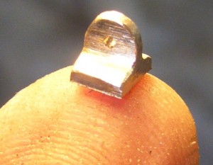
Here’s a cute picture of the little bracket I made to attach the new spring. I filed it from one of the brass 13A plug pins that I got the screw terminals from and silver-soldered it onto the contact end of the flexible strip (that’s a 0.8mm diameter hole):

switch2

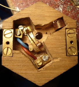
This photo shows the final setup. The brass peg to the left of the flexible contact (a screw with the head filed down) is there to ensure the torsion spring can’t swing to the left and disengage from under the button:

switch3


Now that I had a working bellpush, I wanted to make a little video to show it off. I don’t have an electric bell here and the continuity buzzer in my multimeter doesn’t sound impressive enough, so I hooked it up to something else instead: