A few weeks ago, a fellow concertina restorer contacted me to ask if I might be interested in manufacturing reproduction Wheatstone-style nickel-silver-capped buttons. As it happened, I had already been planning to develop the tooling to make this style of button for use on my own instruments.
I used solid acetal (Delrin) buttons on my own first instrument. They work fine and I expect them to last a long time if not abused, but I can’t deny that they have a ‘cheaper’ feel than metal, that isn’t really in keeping with the materials used for the rest of the instrument. As the maker, I know each button was lovingly hand-turned and polished, but a layperson could assume they were squirted out of a machine by the million like toothpaste tube caps.
Historically, cheaper instruments had bone buttons, whereas high-end instruments usually had nickel-silver (German silver) buttons. Solid nickel-silver buttons are surprisingly heavy, so manufacturers typically either drilled a hole in them and soldered a thin cap over the hole, or pressed a cap from thin sheet metal and used it to cover a lightweight core made from wood. Wheatstone later switched to making the cores from plastic because it is less prone to splitting.
My collaborator sent me a sample vintage Wheatstone button, and I started reading about press tool design. It was the first time I’ve made this sort of tool and possibly my most ambitious toolmaking challenge to date, so it took me a little while and I made a few mistakes along the way.
I did nearly all of the toolmaking on my little Taig micro lathe; it’s a surprisingly capable machine if you keep your tools sharp and stick to very light cuts.
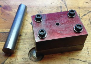
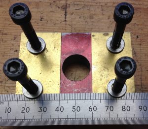
I made the blanking punch from an 18mm silver steel bar, and the die from an O1 steel plate with a 1″ thick mild steel guide block bolted over it.
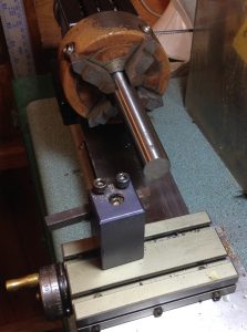
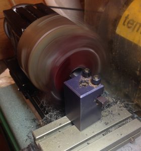
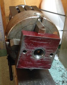
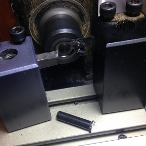
Boring out the guide block on the Taig lathe; this was a bit scary swinging such a heavy lump of steel at the lowest speed the lathe can manage:
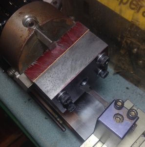
Then I unbolted the guide block without moving the bottom plate from the chuck, and bored the hole in the die slightly larger to give the appropriate clearance between the punch and die.
Brass spacers guide the nickel silver strip through the tool.
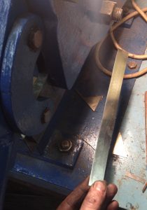
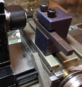
Shearing off a strip of 0.5mm nickel silver to feed into the blanking punch.
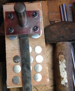
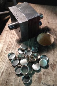
The blanking punch produces 18mm discs. I drive it with a sharp whack with a lump hammer rather than using the press, both because it’s quicker and because a sudden shock will tend to shear the metal cleaner with less distortion than slowly pressing the punch through it.
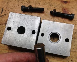
The next tool was the cupping die, so-called because it turns the flat discs into cups. The bottom die has a recess bored into it to hold the disc perfectly centred over the hole.
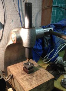
After putting the disc into the die, I clamp the guide plate over it (light finger pressure is sufficient), then drive a polished silver steel punch with rounded corners down through the die with my arbor press.
This produces shallow, large-diameter cups. They are already starting to look a little bit like buttons if you squint.
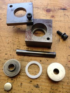
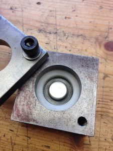
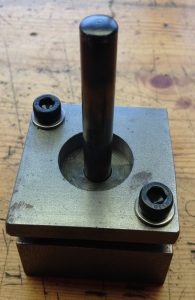
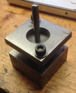
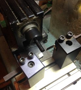
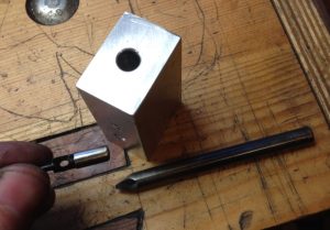
Next I need to take the cups through a series of redrawing stages; each one reduces the diameter of the cup by around 20% while also increasing its depth. If you tried to go straight from a flat disc to a finished button cap in one stage, the walls would wrinkle and jam in the tool because there’s a limit to how much you can alter the shape of the part in each pass. The square parts in this photo are a mild steel tool holder, then there’s the silver steel punch, die, and guide, with an acetal spacer between the two. I later figured out that this stage works more reliably if I clamp it together very lightly with spring washers, so it’s possible for the guide to lift slightly if it has to.
The first redrawing die is a reverse die; this means you place the cup over it and the punch turns it inside out. In hindsight this probably wasn’t the best idea, but it does work. I did it because it looked easier to make, and I wasn’t aware of the drawbacks involved in reverse redrawing.
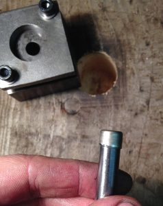
The cup comes out of the bottom of the die stuck on the end of the punch. Sometimes they can be very tight and difficult to remove. An industrial drawing press has something called a ‘stripper’ that holds onto the part while the press yanks the punch back up through the die with a lot of force, but with my low-tech tools I have to resort to manually knocking them off using a bar with a hole in it.
The rest of the redrawing dies are direct dies; i.e. you place the cup into a large section at the top of the die, then the punch forces the cup through a narrower neck with a rounded corner at the top.
Pushing the punch through the die with my Jones & Shipman arbor press. I was a little concerned before starting the project that it might not prove strong enough for the task, but in fact it is quite capable of bursting open the top of the cup if it gets stuck in the die.
A successful second redrawing.
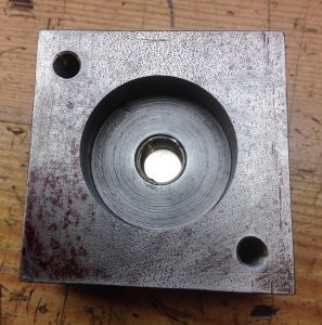
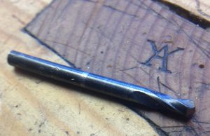
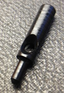
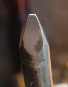
The two diameters inside the top of the die need reaming with a purpose-made D-bit. By making a single tool that reams both diameters at once, it was also able to form the rounded transition at the top of the neck (this is a very important feature of the die because the metal won’t flow smoothly around a sharp corner).
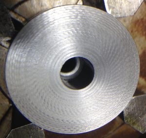
The inside of the final redrawing die, after reaming with the above tool. Of course I also had to polish it smooth after hardening it to keep the friction as low as possible. You can’t see it in this picture, but the neck is quite short, with a slightly larger diameter section below it.
I found it wasn’t necessary to clamp the guide block down on the last redrawing tool:
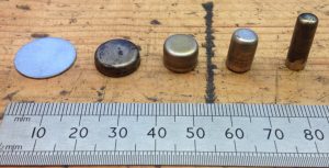
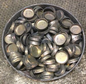
Here’s the full sequence of parts produced by the above stages. The blank disc is 18mm diameter, and the final cap is about 5.8mm diameter by 15mm deep:
I encountered quite a few problems along the way; in particular I found that the parts often jammed in the die and burst because the bottom edge of the cup had become thickened. In theory you can work around that by increasing the clearance between the punch and the die, but I found that caused other problems, so before the second and third redrawings I instead manually grind a little bit of thickness off the lip of the cup, just enough to allow it to go smoothly through the die.
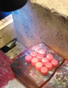
I found that I got better results if I annealed the cups between stages. It probably isn’t strictly necessary to anneal every time, but it did seem to help them draw more smoothly with less force. In my initial experiments I annealed them with a blowtorch, which works OK but takes a while and uses a lot of gas if you’re making lots of them.
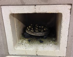
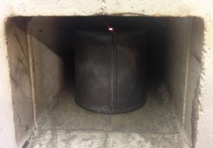
I next tried putting them in my electric heat treatment oven.
This did a nice consistent job of annealing them, but because they were exposed to the oxygen in the oven for a long time, they built up quite a lot of scale that caused so much extra friction inside the die that I had to spend ages polishing it off before they would redraw smoothly.
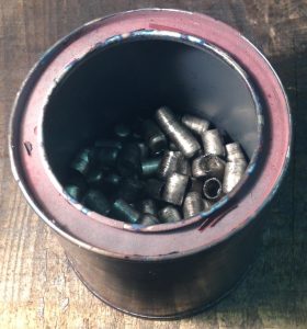
Next I tried putting them in the electric oven inside a tin with a little hole in the lid.
The buttons were coated with grease used to lubricate the drawing process; as this burnt off, it displaced the oxygen inside the tin and generated a little flame at the vent hole:
Much better. They came out of the tin a little sooty and discoloured, but nice and soft with no significant scale buildup. I cooked them at 450°C for an hour, which is probably overkill but didn’t do any harm. I will experiment with reducing the time when I do the next batch.
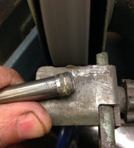
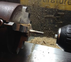
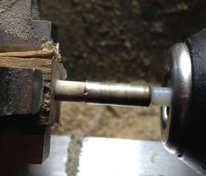
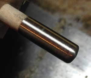
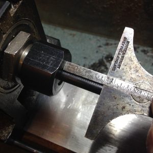
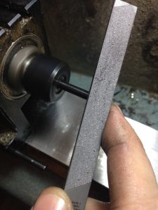
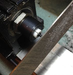
After the final redrawing stage, the caps were approximately the right diameter but a bit lumpy and too long. To cure this, first I mounted each cap on a tapered wooden mandrel on the lathe and used a wide flat fine file to smooth them out:
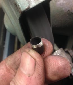
A quick polish brought out a nice shine:
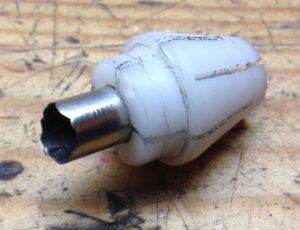
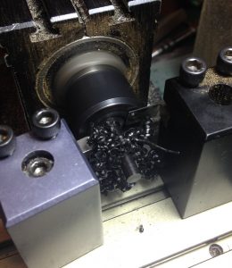
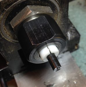
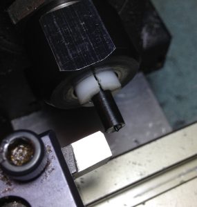
I made a special soft collet to hold the buttons bottom-out in the lathe while I parted them to length. Incidentally, those random frilly edges are very typical of drawn sheet metal parts and are called ‘ears’.
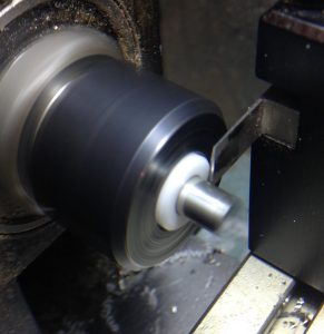
There is a depth stop inside the collet, so I was able to lock the lathe carriage in place and quickly part off all the caps to the same length.
With the metal caps finished, I now needed to make the acetal cores. They are almost identical to the solid acetal buttons I made for the first instrument, apart from not bothering to give them a nicely-domed head or polish them.
1. Extend an appropriate length of ¼” black acetal from a collet.
2. Face off (only necessary on the first button from a new piece of stock).
3. Turn down to the right diameter to fit inside a cap. This is trickier than you might think because the acetal is very bendy and wants to deflect away from the cutting tool, particularly at the end furthest from the collet. It helps to use a razor sharp tool and cut to the final diameter in a single pass at quite a slow feed rate. Even so I had to experiment quite a bit before I was reliably producing cores that fit nicely.
4. Roughly round over the corner with a file. This doesn’t need to be pretty because it won’t be seen, but it is needed to allow the core to go all the way into the cap, because the inside of the cap is slightly rounded.
5. Part off to roughly the right length.
6. Put the core in another specially-made collet with a depth stop in it, with the bottom end facing out.
7. Face to exact length. Note that I have the carriage stop set to allow me to repeatably turn up to the transition between the pin and the main body of the core, so for this stage I clamp a spacer between the stop and the carriage that is the same thickness as the length of the pin.
8. Turn the pin to diameter in one pass. If you look closely you will see I ground a flat on the corner of the lathe tool in order to form a fillet at the root of the pin; this greatly reduces the likelihood of the pin breaking off if the button gets knocked hard.
9. Chamfer the point of the pin with a file.
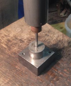
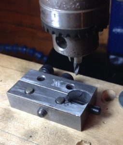
Next we have to drill the cross hole and countersink both sides. The original Wheatstone core had a 2.5mm hole, but I find that 3mm holes work better with modern 0.85mm bushing cloth. To avoid needing to spot each hole with a centre drill, I instead got a 3mm twist drill and ground it as short as possible to make it very rigid so it doesn’t deflect and drill the hole off-centre.
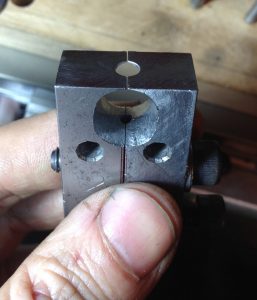
This is the same fixture I used to hold the buttons I made for my first instrument, but I have modified it a bit and I’m now doing both the drilling and countersinking on my CNC milling machine instead of the manual drill press. Firstly because the mill is more rigid and accurate, secondly because it has a quick change toolholder that lets me swap between tools and know the tip of the tool will be the same distance from the spindle nose each time, and thirdly because I was able to write three very simple macros that repeatably perform exactly the same operations each time without relying on manual depth stops.
The pins in the mounting board correspond with the holes in the fixture and allow me to turn the button 180° to countersink the opposite side of the hole. The fixture is actually inaccurate by about 0.3mm, but because the error is the same every time I was able to program the machine to compensate for it and get the second countersink to line up pretty much perfectly (this wasn’t the case with the manual drill press, leading to the countersinks all turning out a tiny bit misaligned; probably not enough to significantly effect the operation of the action but enough to annoy the perfectionist in me!).
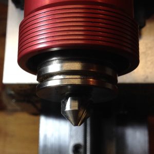
The countersinking bit. It has a 10mm shank and all my quick change toolholders are imperial sizes, so I had to turn a special adapter sleeve to avoid having to hold it in the drill chuck, which would have caused problems with the tool Z offset changing every time I swapped back and forth between the drill and the countersink.
A finished button core. With a little polishing, this would be perfectly acceptable as a solid acetal button.
I made a special tool to crimp the caps onto the cores. The Wheatstone sample had a single small dot, presumably made by something like a centre punch, but in my experiments I found that if I instead made a punch with a slightly blunt chisel-shaped tip, it takes several times the amount of force to pry the caps off.
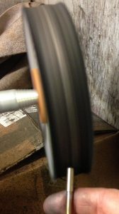
A quick final polish on the buffing wheel:
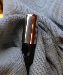
Followed by buffing with a soft cloth to remove the polish residue:
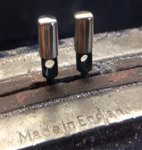
Here is one of my buttons next to the Wheatstone sample. The main difference is the increase in the diameter of the cross hole:
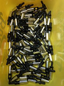
And here is my full first batch of buttons (I would have made more but I ran out of materials):
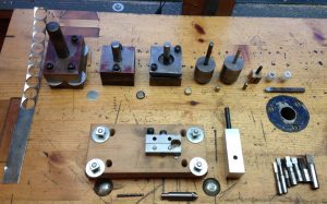
Here is the full lineup of tooling I made for this process:
This has proved to be quite a challenging project at times, and as always there are things I would make slightly differently if I knew then what I know now, but I am very pleased with the high quality of the resulting buttons and I’m looking forward to building an instrument that includes them.
Some future experiments:
- Materials. I’m pretty sure this tooling would work with other non-ferrous metals. I have read that a fairly high percentage of the population is sensitive to nickel and might not be able to comfortably use an instrument with nickel-silver buttons. Alternatives include copper, various alloys of brass/bronze (some of which are more tarnish-resistant than others), or a silver alloy like sterling silver or Argentium. Aluminium could work but may be a bit soft and prone to oxidation. Titanium would be interesting but I’ve not yet worked with it and don’t know much about how easy it is to press. I’m not sure how well the tooling would cope with stainless steel, as it’s much harder.
- Diameter. English-made concertina buttons have been made in a variety of sizes between about 4.5mm and 6.5mm (German-made ones were sometimes even larger). Preferred diameter comes down to each player’s fingers and playing style, though there are practical limitations too (e.g. there may not be room in a very dense action for large-diameter buttons). The most common size for English-system instruments seems to have been 3/16″, or about 4.75mm. I don’t think it’s a coincidence that the cores of the buttons I’ve just made are also approximately 3/16″, which gives a cap diameter of about 5.7mm. It would be interesting in the future to try making another final redrawing tool that produces 3/16″ caps, and possibly yet another one to produce 1/4″ (6.35mm) caps.
- Tip shape. Another aspect of button design is the shape of the tip. From discussing this with players, it seems that some prefer very flat-topped buttons, others very rounded, and yet others are happy with a compromise somewhere in-between, with a very slightly convex top and more rounded corners, as in the caps I have just made. I think it would be fairly easy to make the caps more rounded by making a new final punch with the same diameter but a hemispherical tip. Making caps with a flatter top would be slightly trickier, because if the punch is too flat it causes a concentration of force at the corner which tends to burst the cap in the die. The answer might be to make the caps slightly rounded as above, then use a different tool that compresses the cap between a flat punch and a flat anvil (or perhaps the punch might even need to be slightly concave). More experimentation required.
- Length. Not exactly an experiment, but just to point out that because I’m turning the cores manually and the caps come out of the press several mm longer than necessary, it would be trivial for me to make buttons that are up to about 4mm longer or shorter for different depths of action box/thickness of end plate, or for a player who prefers buttons that are extra long or extra short. I can also alter parameters like the length and diameter of the pin and the location of the cross hole if necessary.
Well done Alex. Very nice. Gys
Thanks Gys!
I made a set of buttons using only two drawing dies. They would be the second and last of your set. With an anneal in between. I used metal really too thick to start with, and if I were to do it again, I would start with thinner stock . I had no wrinkling, but the blank needs to be held captive by the guide block so it has to flow over the corner ( very rounded and polished ) into the hole, without being able to lift at all. You should be able to do the draw in one go. If you look at the deep drawing dies for ball point pen barrels, they manage very deep draws in the first die, while the rest reform the initial tube to the different diameters needed. I have a flywheel press that I use, but hydraulic is best for slow but constant feed to avoid the tearing from a quick shove. If I try again, I will make a die using soft urethane in a captive space as the female part of the die after the guide hole.
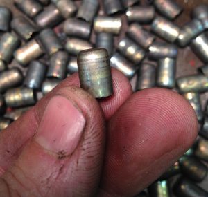
Cartridges are drawn in a few steps like yours because of the thick base needed to resist the pressure and provide depth for a primer, but things like pen caps are not.
Best, Dana
Thanks Dana. Based on what I read about deep drawing beforehand (some of which was about tools for drawing copper bullet jackets), a roughly 20% reduction per stage seemed like a reasonable design target. I have since learned that the first stage can have a much higher reduction than the subsequent stages. My first two stages are constrained to follow the die corner to some extent, but the second two aren’t: I had read that it wasn’t necessary to do so if the the reduction ratio is low enough and the stock thick enough (thinner stock is more prone to wrinkling), and I have found that to be true in my case. I’m using an arbor press with a long lever and am able to lean on the end of it to push the punch through pretty slowly and smoothly, which does seem to help.
If in the future I find I’m making hundreds and hundreds of button caps I will probably remake the tools to try to reduce the number of stages (maybe combining the first two stages into one would be a good start), but for now I’m happy with the results I’m getting with this setup even if it isn’t as efficient as it could be.
Pingback: Introducing the Holden Blackbird – Holden Concertinas