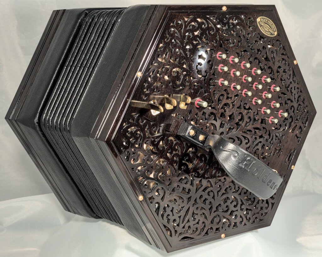
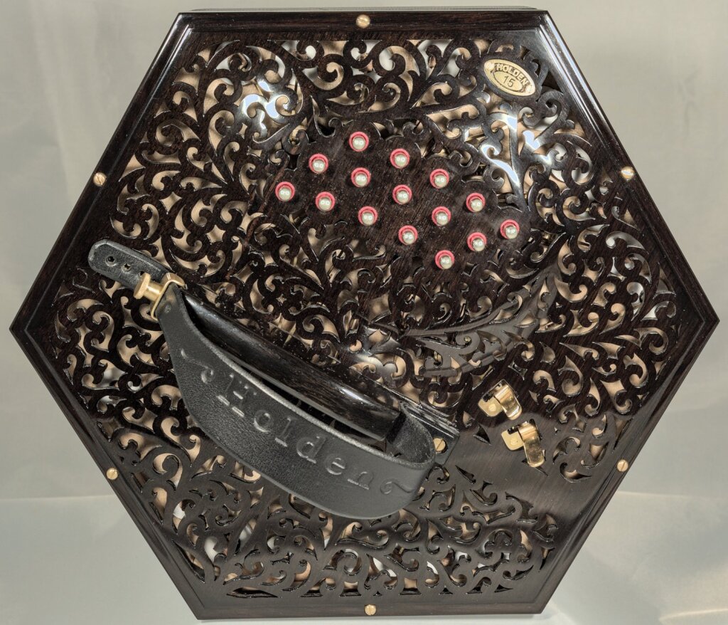
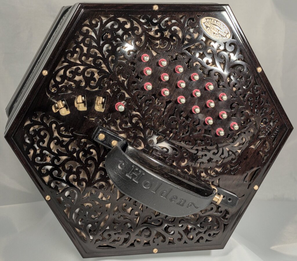
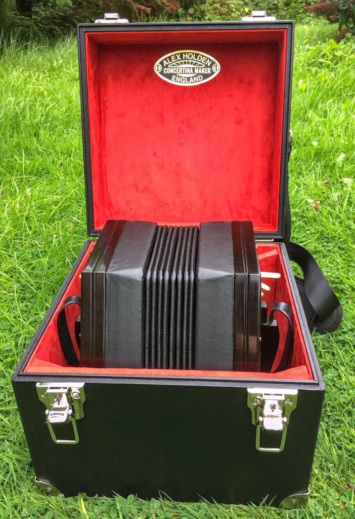
My fifteenth concertina was a bass G/D anglo, i.e. one that plays one octave lower than a standard G/D like No. 6, with 34 buttons and five latchable drone levers.
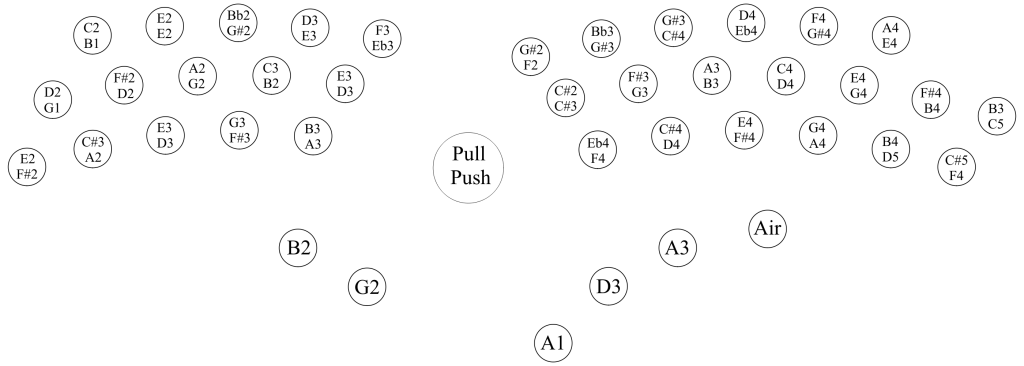
Button Layout
Specification
- G/D bass Anglo.
- Custom button layout with 15 buttons on the left hand and 19 on the right.
- Two latchable thumb-operated drone levers on the left hand and three on the right.
- 4.6mm nickel-silver capped buttons.
- 7mm tall buttons with 3mm travel.
- 2:1 action lift ratio.
- Six sides, 8.75″ (222mm) wide.
- Ebony-veneered action box walls.
- Ebony borders with ogee moulding.
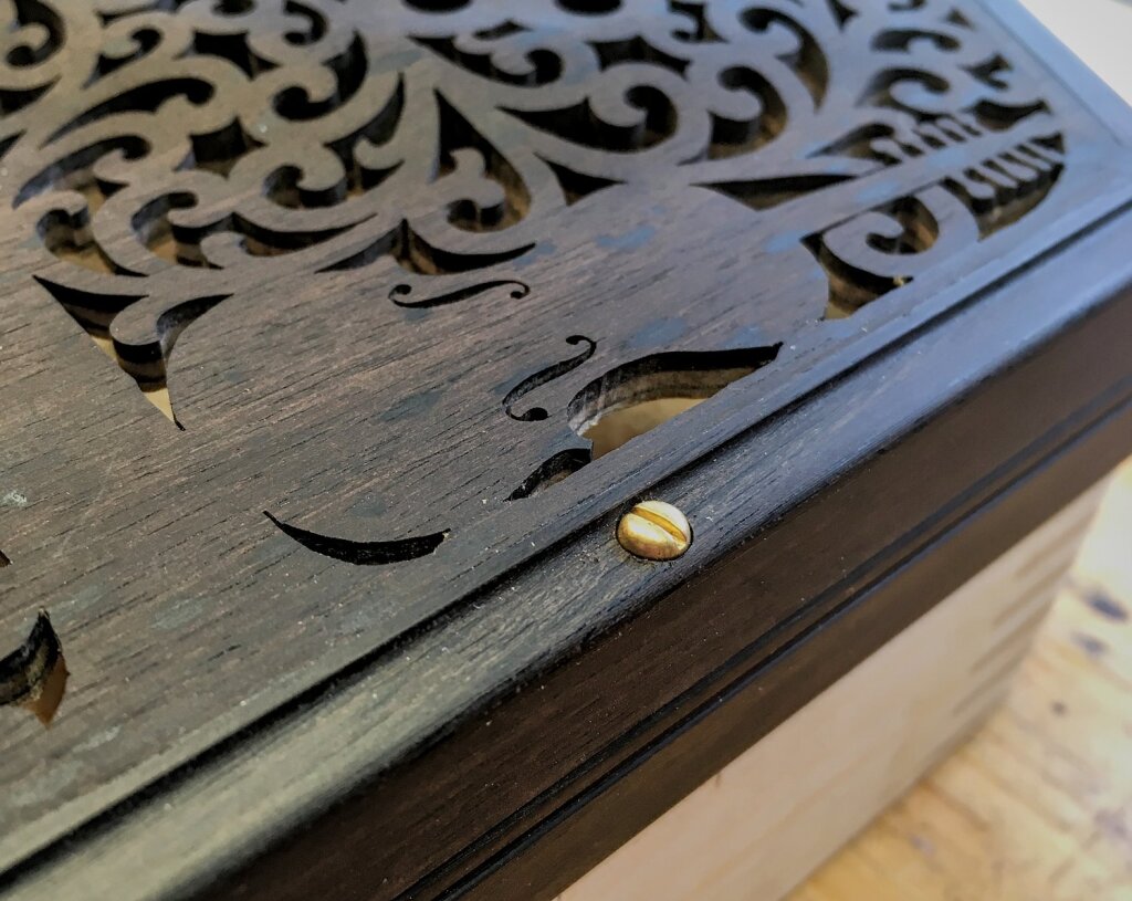
- Raised laminated ebony end plates with fancy fretwork.
- Bog oak curved-top hand rails.
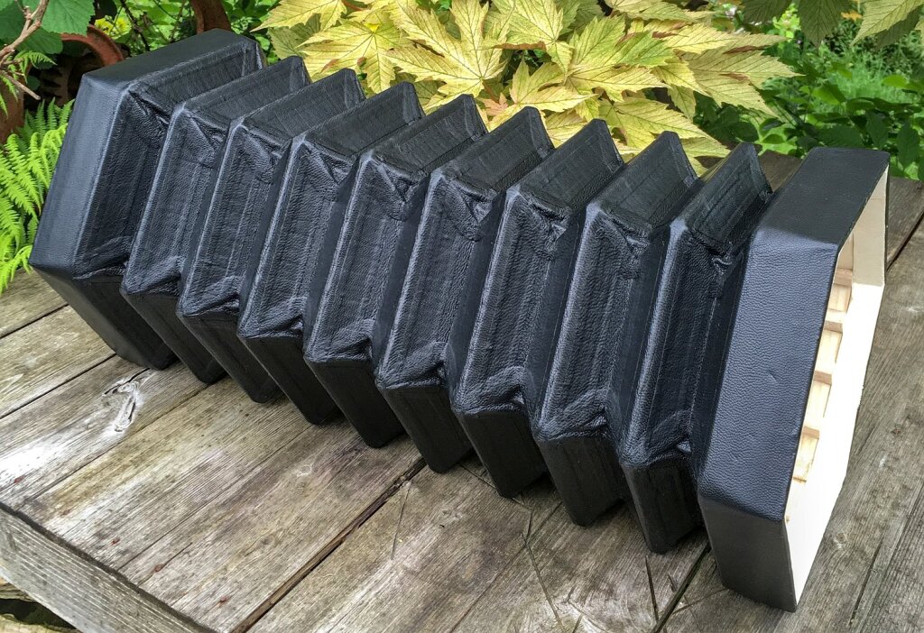
- Eight-fold bellows with full goatskin leather covering.
- Red button bushings.
- French polished finish.
- Brass sheet action levers.
- Brass reed frames.
- Solid sycamore action boards.
- Solid sycamore reed pan boards.
- A4=440Hz, equal tempered tuning.
- Weight: 2935g.
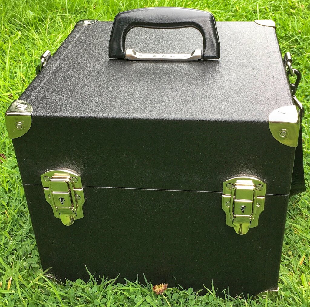
- Deluxe hard case with red suede lining and shoulder strap.
Exterior
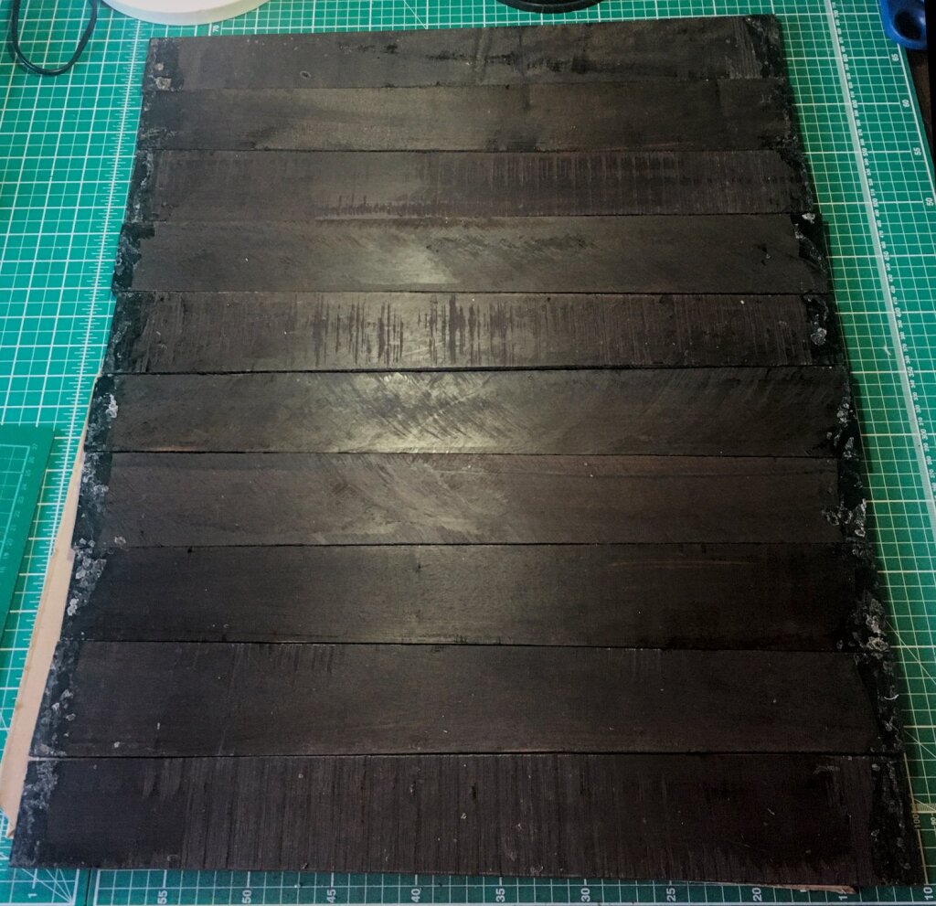
My client wanted the exterior wood of the action boxes to be genuine black ebony, but I struggled to find any suitable wide ebony boards for sale in the UK. After some searching I found an exotic wood supplier who sold me a set of ten Indian ebony guitar fingerboard blanks. These blanks are rough sawn, not perfectly straight, about 530mm long by 73-64mm wide (tapered). I didn’t use all of them on this project: I have enough left for a few more sets of action box wall veneers. At the time of writing, Indian ebony, although fairly rare and expensive, is not listed in the CITES appendices.
It was a straightforward process to resaw some of it into thick veneers, drum-sand them smooth, and glue them to the action box sides.
The ebony’s grain pattern is fairly subtle but quite attractive close up. The colour isn’t jet black; it’s more of a very dark chocolate-brown, though that is only obvious under bright lighting.
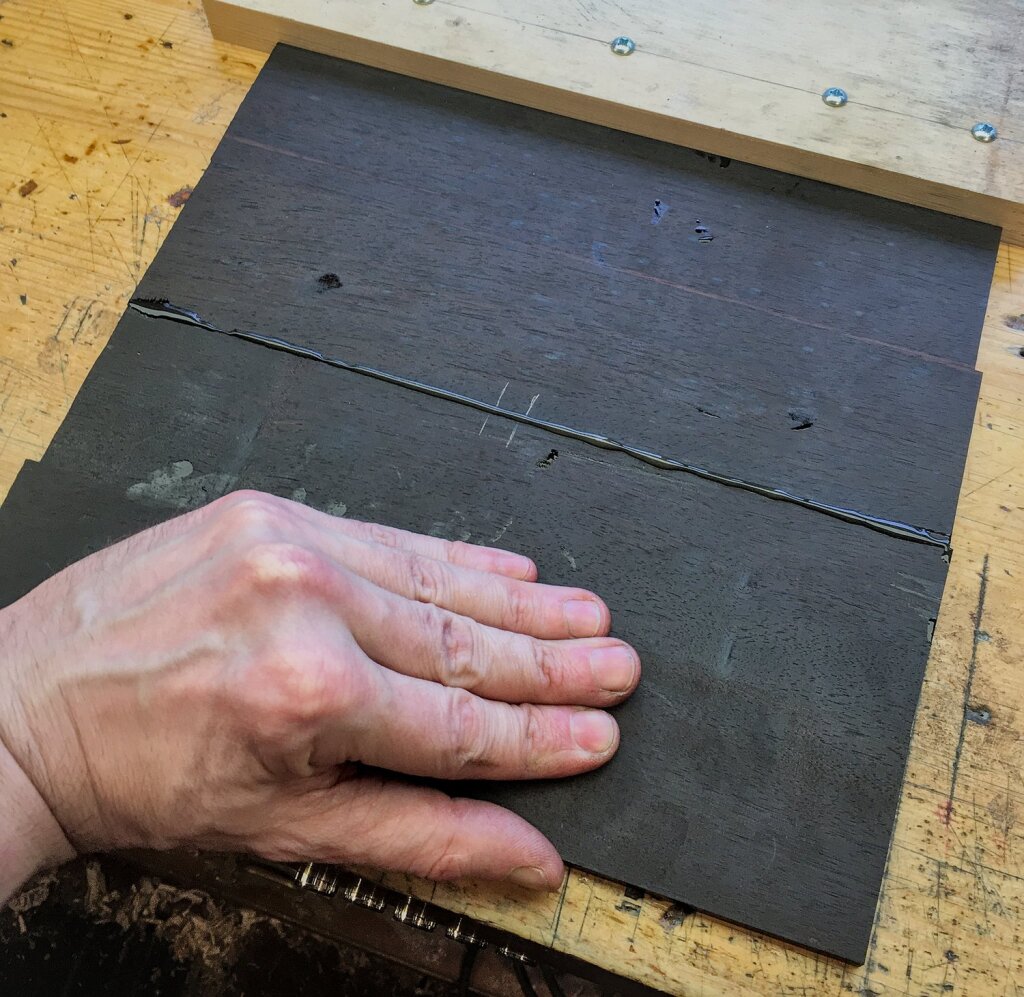
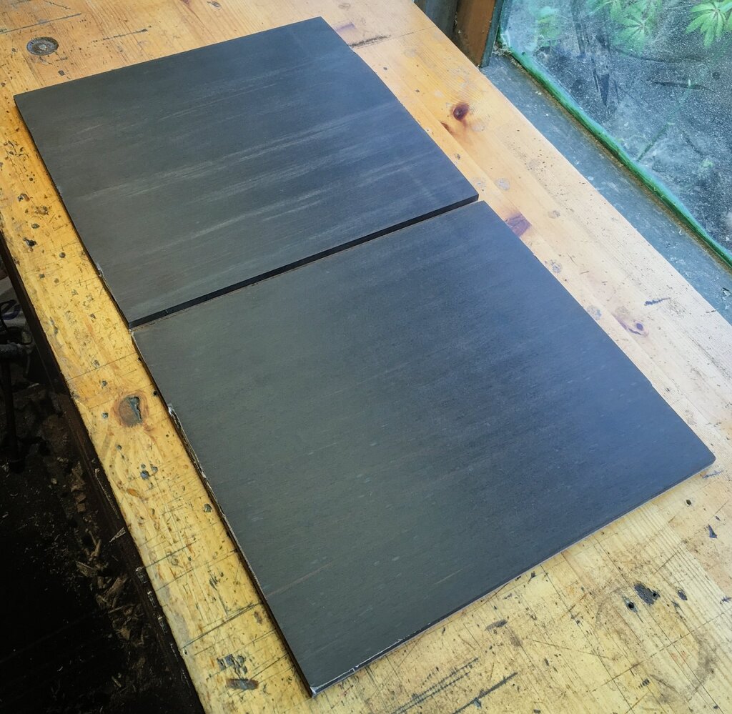
The raised end plates were more challenging to make because they needed to be much wider than the fingerboard blanks. I also wanted the raised area to be solid, but the thinner parts to be laminated onto a strong substrate with cross-grain fibres to strengthen the fretwork. After thinking through various possible ways to do it I decided to plane four fingerboards, cross-cut them in half, then edge joint them together to make a pair of wide boards that were about 6.5mm thick.
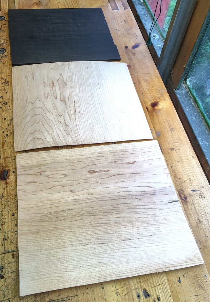
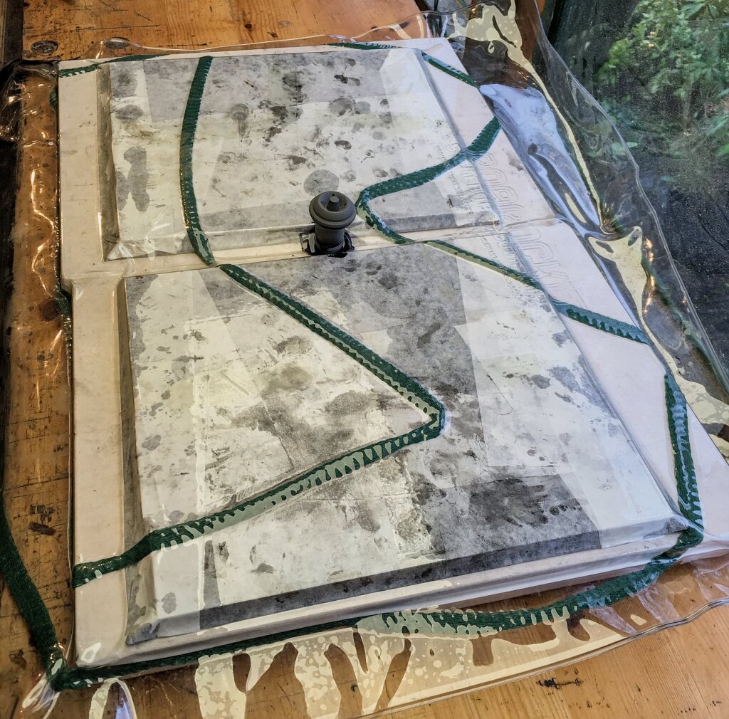
After drum-sanding the wide ebony boards smooth, I laminated them onto two plies of 1.5mm hard maple constructional veneer in a vacuum bag using black-dyed epoxy. The middle ply had perpendicular grain orientation.
After sanding the excess glue off the outside, the resulting laminated boards were nice and flat and it wasn’t too obvious that the ebony was glued together from four fingerboard-width pieces.
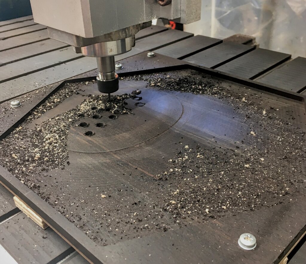
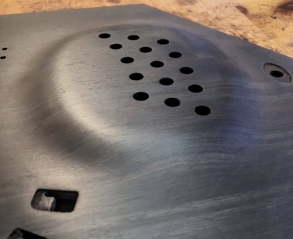
Then I used my CNC router to mould the raised area around the buttons (using a waterline operation), cut the holes for the buttons and hand rails, and profile the perimeter. We spent a while discussing what the shape of the raised plateau should be and the steepness of the slope and whether it should extend below the hand rail etc. There are a surprising number of different variations on the concept of a raised end.
After a bit of hand sanding to remove the tool marks, the raised area looked very smooth and organic.
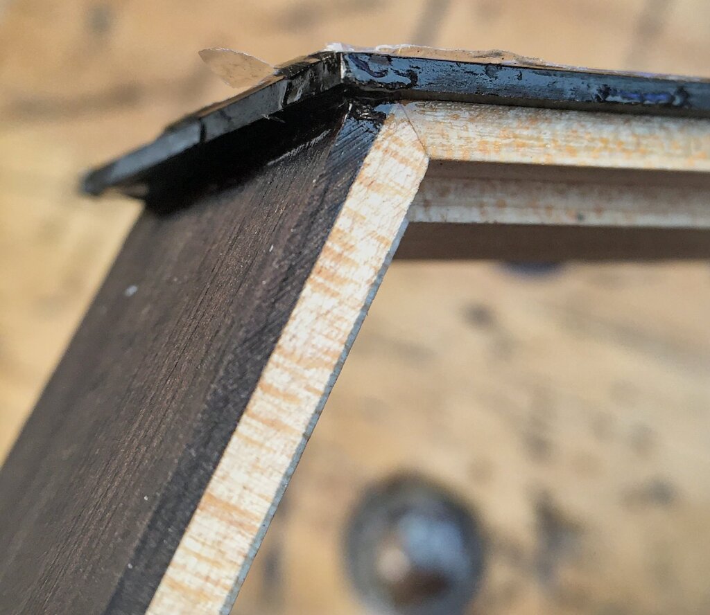
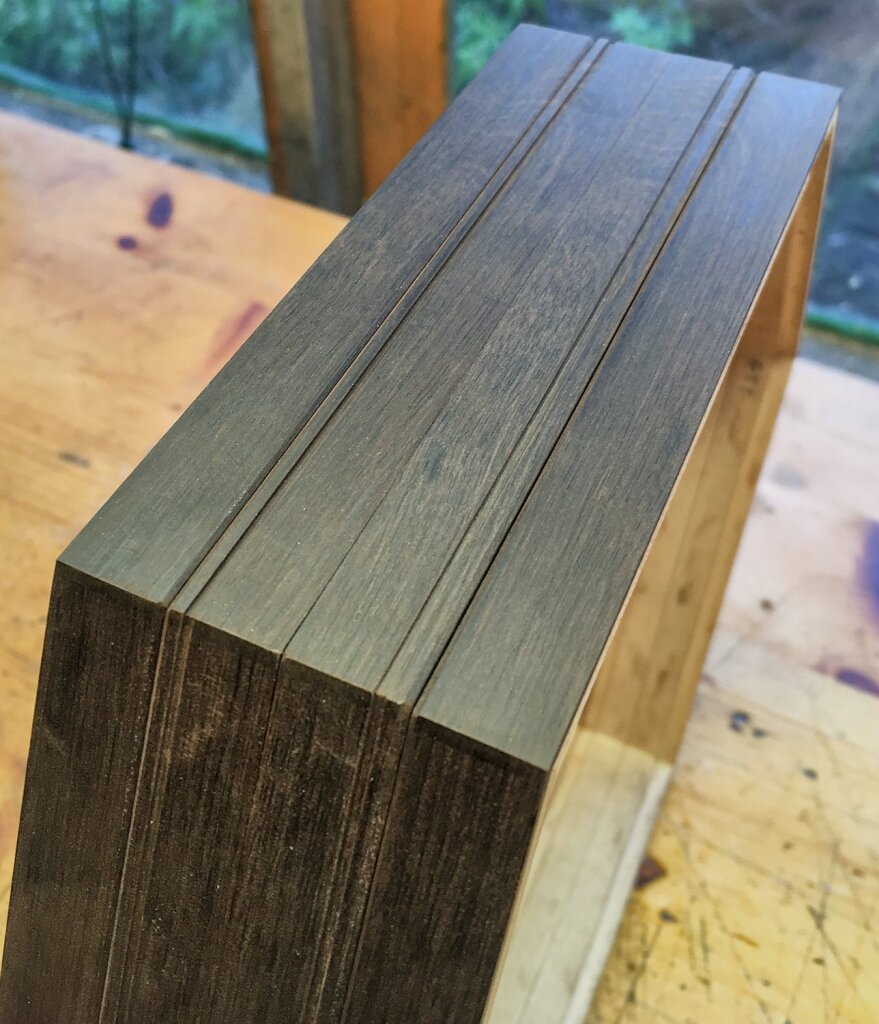
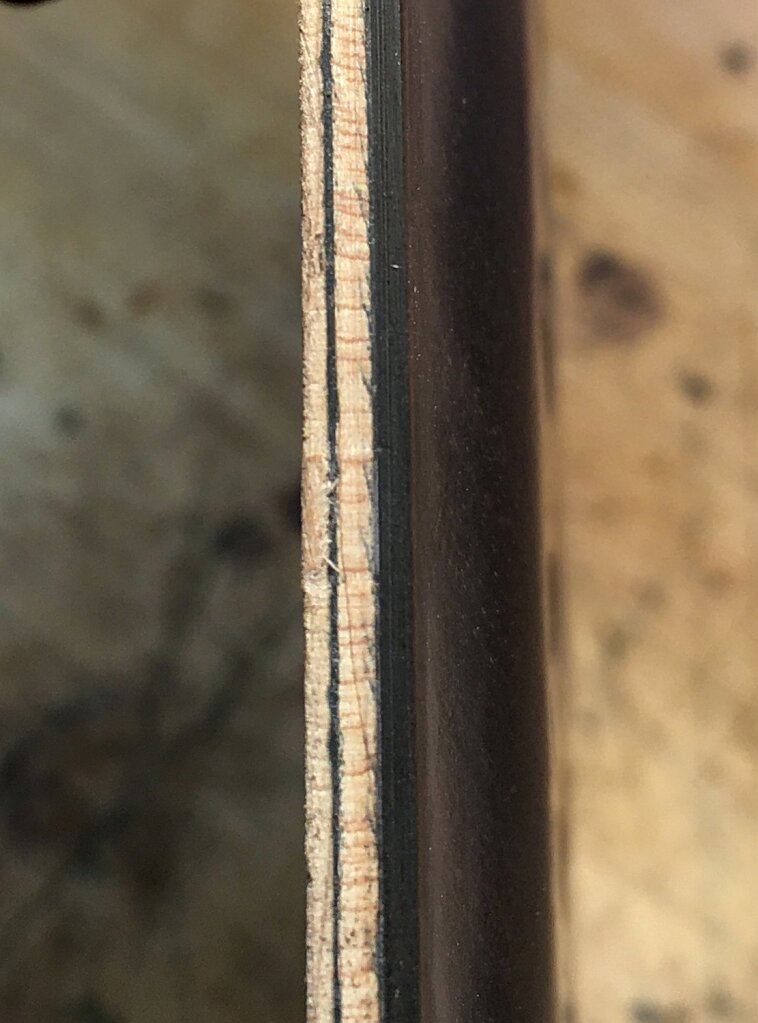
Edge-on, you can see the three layers of the laminated board and the two black epoxy glue lines. The non-raised areas of the boards were about 4.5mm thick and the raised area was 4mm thicker.
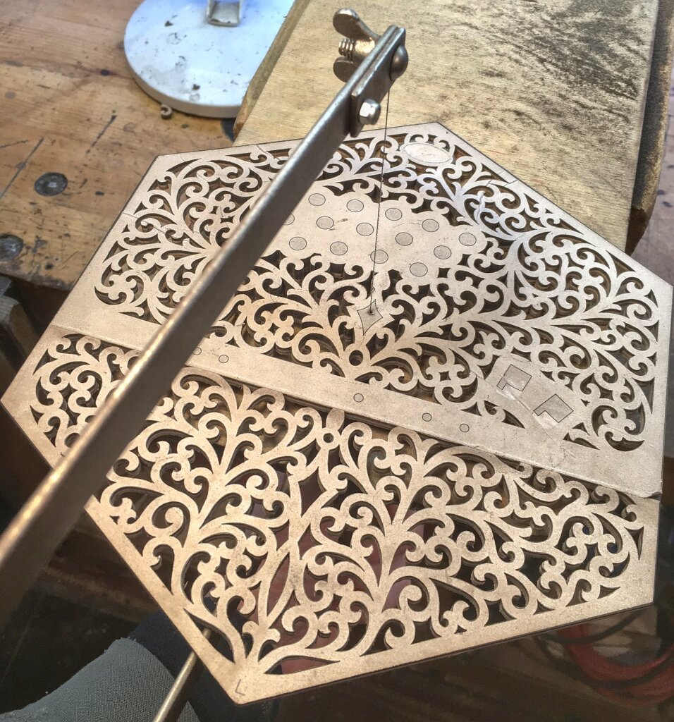
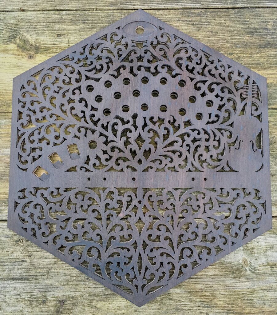
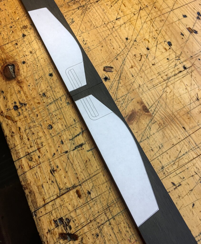
The hand-pierced fretwork was quite a lot of work, but I think the results speak for themselves. I had to print out the templates on two sheets because the design was too large to fit on a single A4 page.
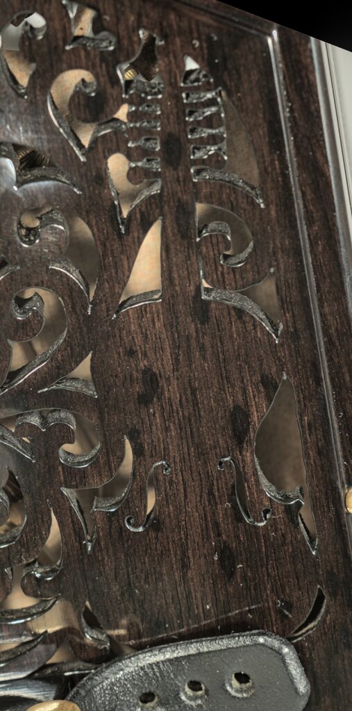
My client asked me to incorporate the silhouette of a Hardanger d’Amore on the right hand as a personal touch.
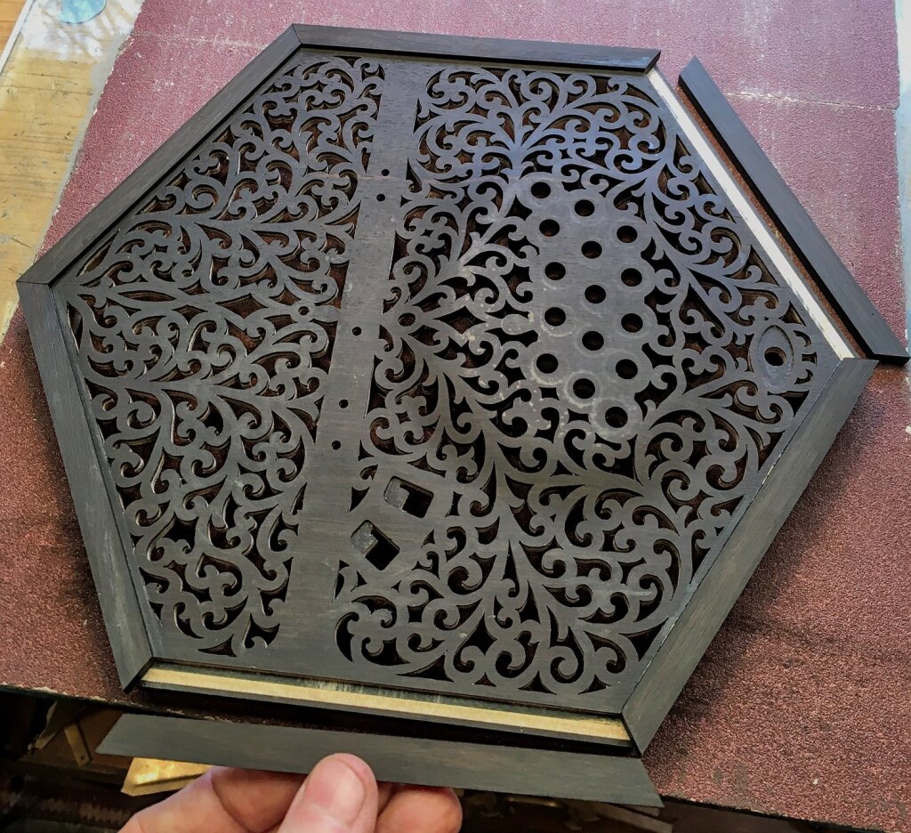
The end plate borders were also made from solid ebony.
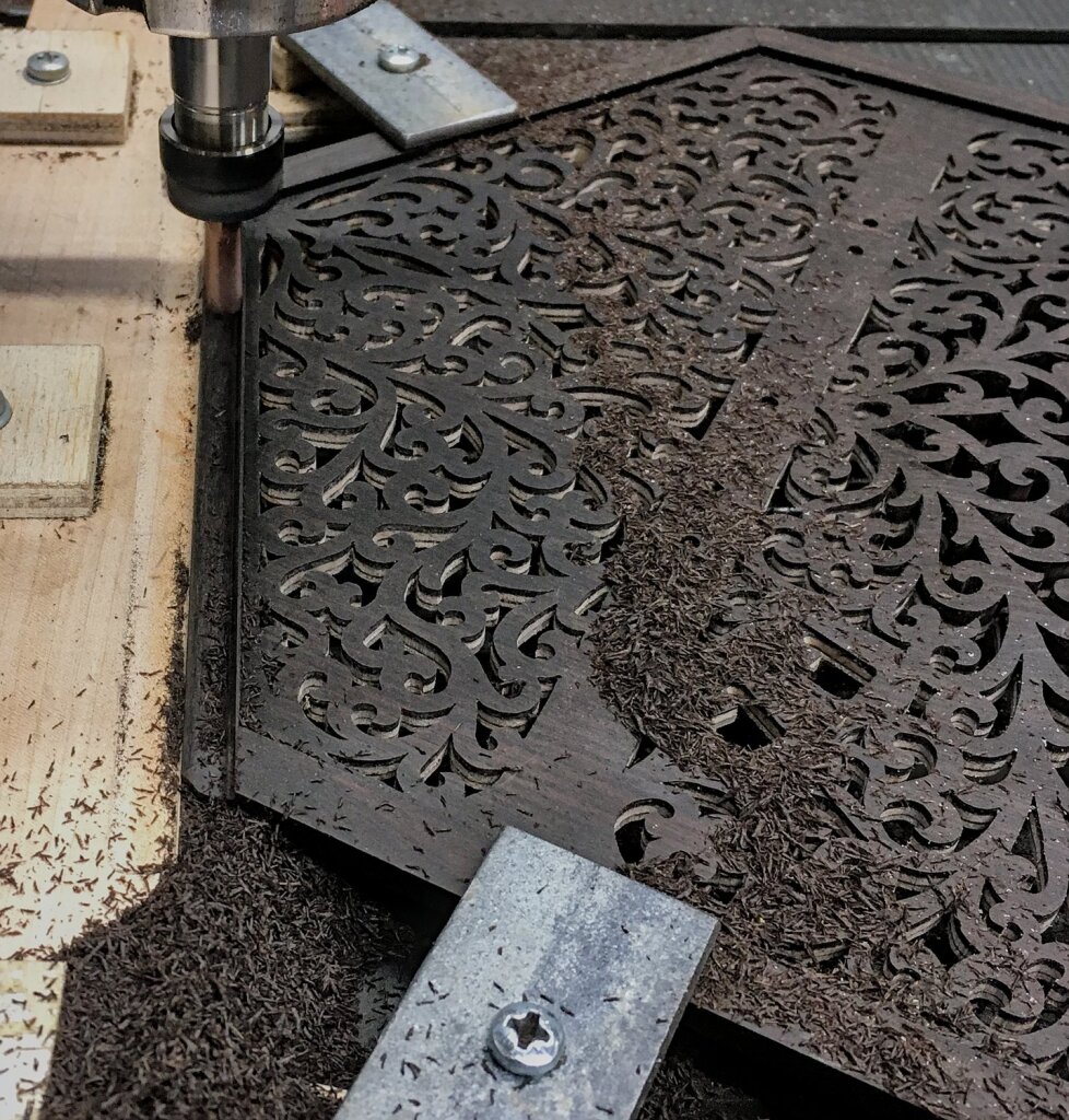
The ogee border was a slightly more refined shape, and I produced it using a different method. Instead of cutting it on the milling machine using a single point flycutter hand-ground to the required profile, I programmed the CNC router to make multiple passes along the profile using a 6mm four-flute carbide end mill with a 1mm corner radius.
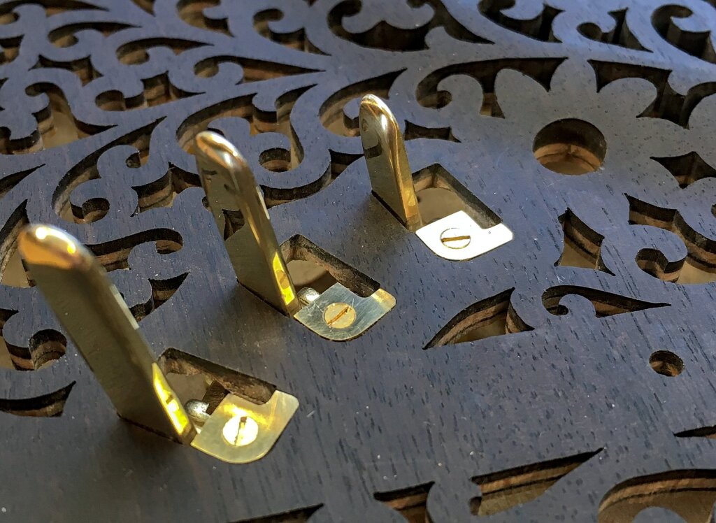
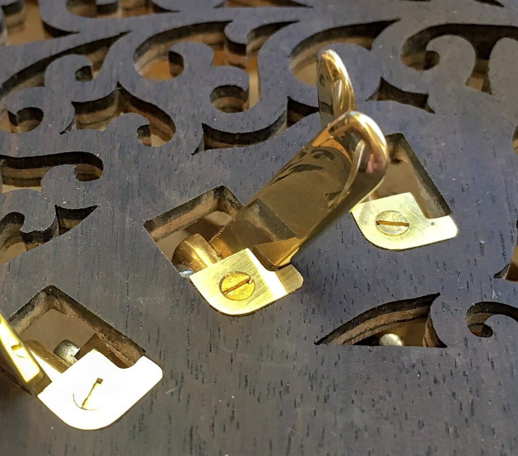
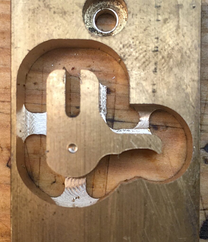
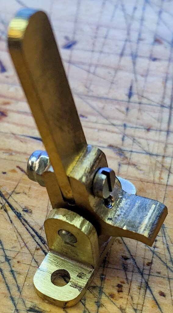
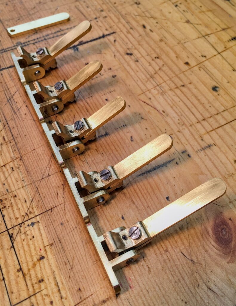
The latchable thumb levers are three different lengths to make it easier to quickly find the right one with your thumb by feel. I rounded off and polished the ends so they don’t feel sharp. After pushing them forwards against a light spring to sound the note, you can optionally flip it to the side so that it is held by a narrow slot. I arranged them along an arc rather than in a straight line to better match the way the player’s thumb pivots.
On the plywood prototype I found that the corner of the wood at the entrance to the slot was prone to wear, so I added small inset brass pieces to the end plate for the lever to slide on.
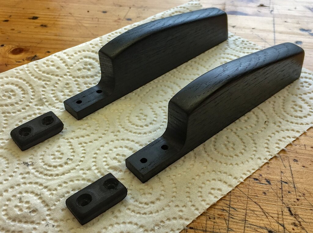
I cut the hand rails from Ukranian bog oak. I thought about using more of the Indian ebony (it probably would have been cheaper than the oak), but I would have had to glue two thin pieces of it together to make a thick enough blank and I thought using a solid piece was probably a better solution.
The bog oak does look nice, though it is a different shade of black to the Indian ebony.
I used a French Polish finish on all the exterior woodwork and contrasting red button bushes.
The thumb air button was a slightly larger diameter than the finger buttons, to spread the extra force required to open the large air pad over a greater area.
The ebony had a slight amount of figuring, particularly the small darker flecks you can see in this close-up shot of the Hardanger d’Amore. The tuning pegs were very small, so I sawed around the whole peg area and then carved the fine details of the pegs into the surface with the point of a sharp scalpel blade. I cut out the F holes very carefully with an extra fine jeweller’s saw blade.
Actions
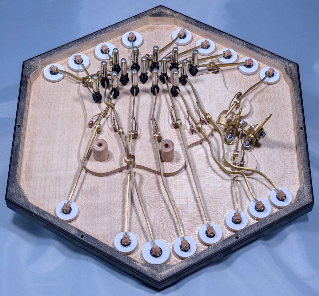
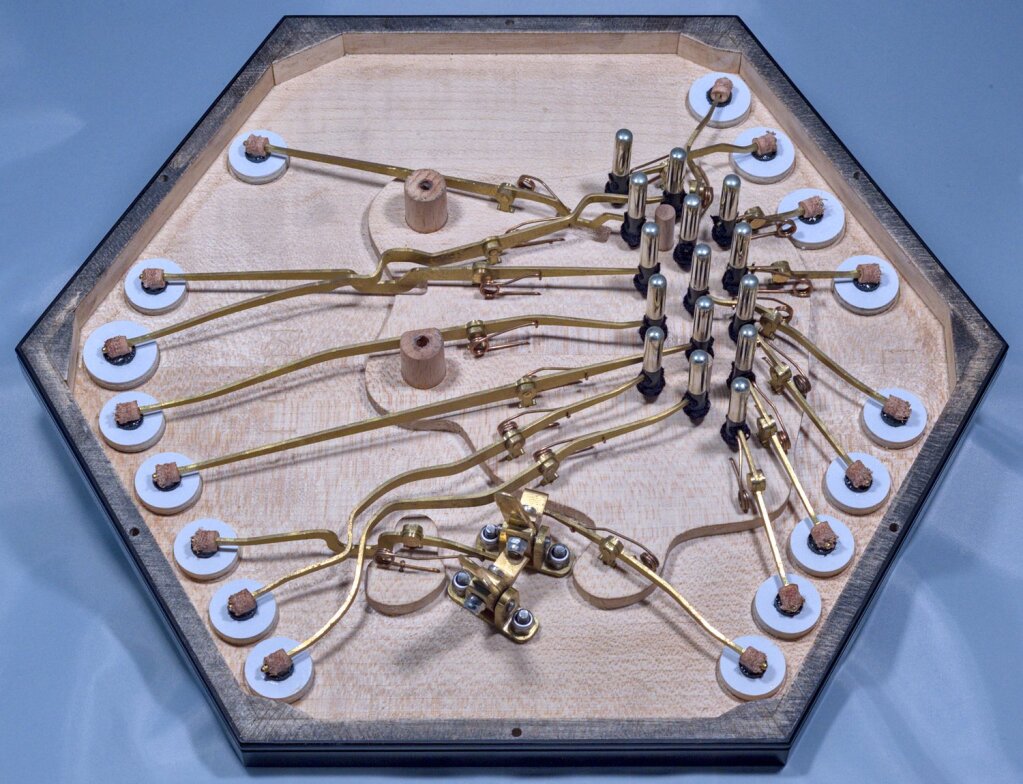
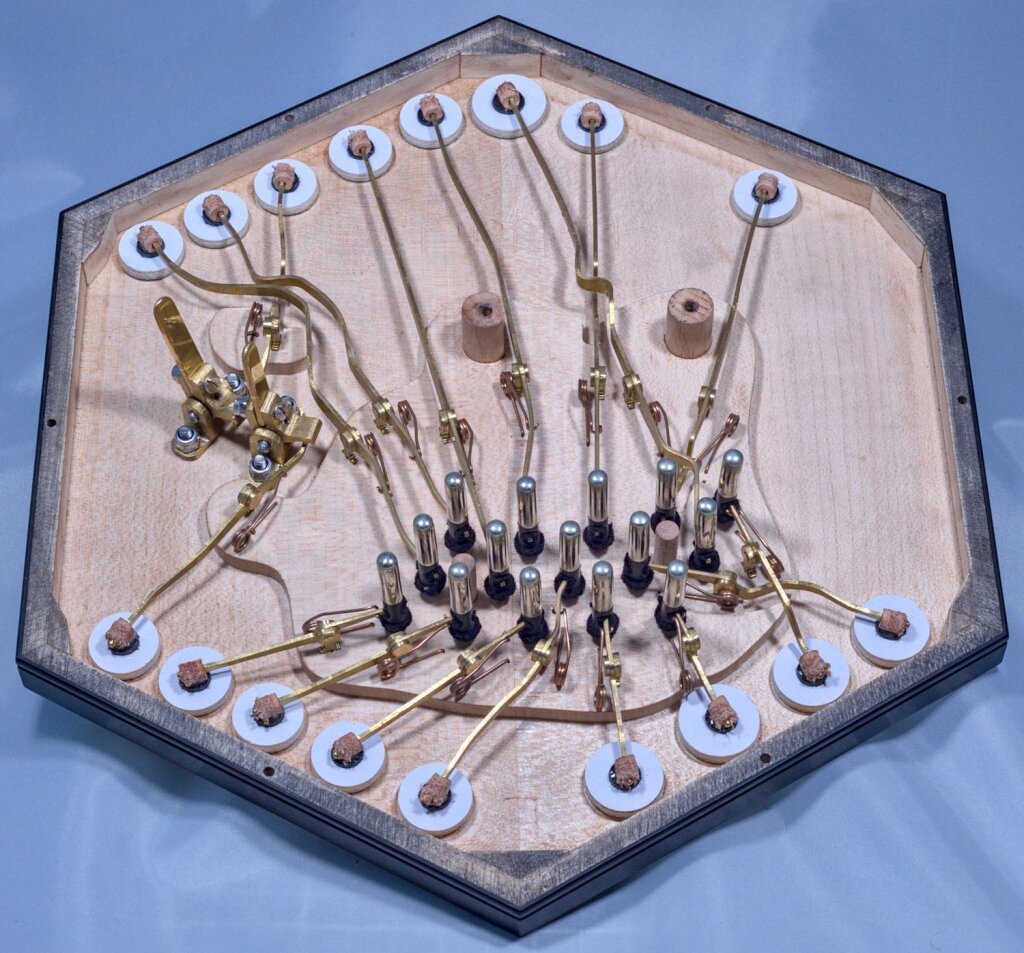
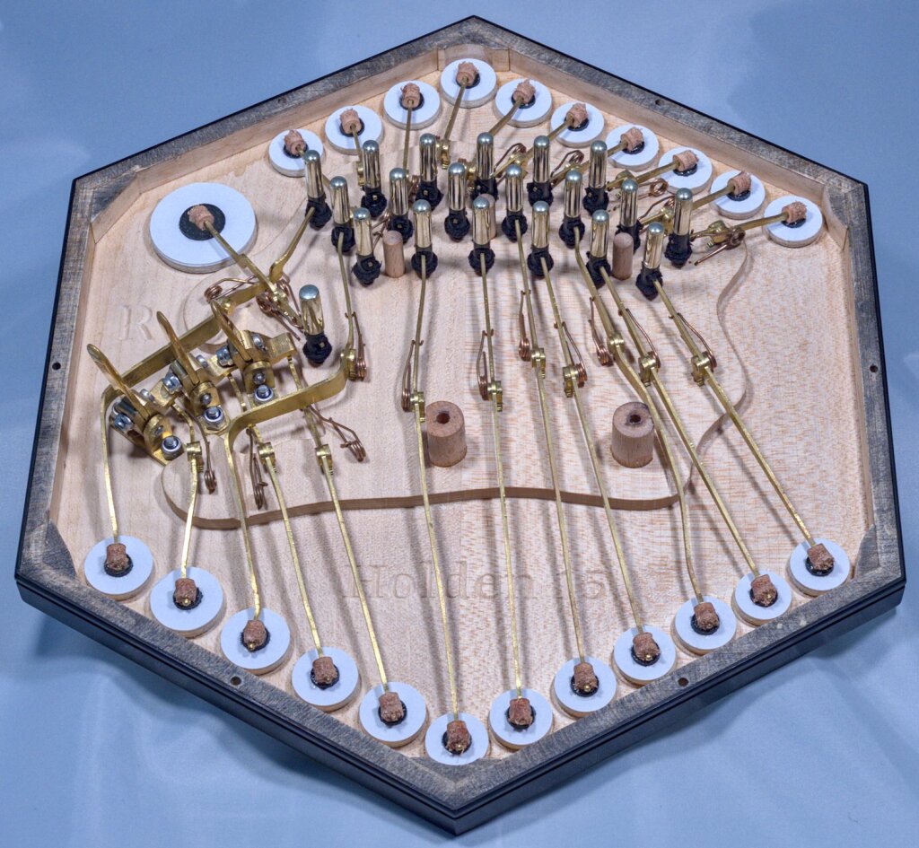
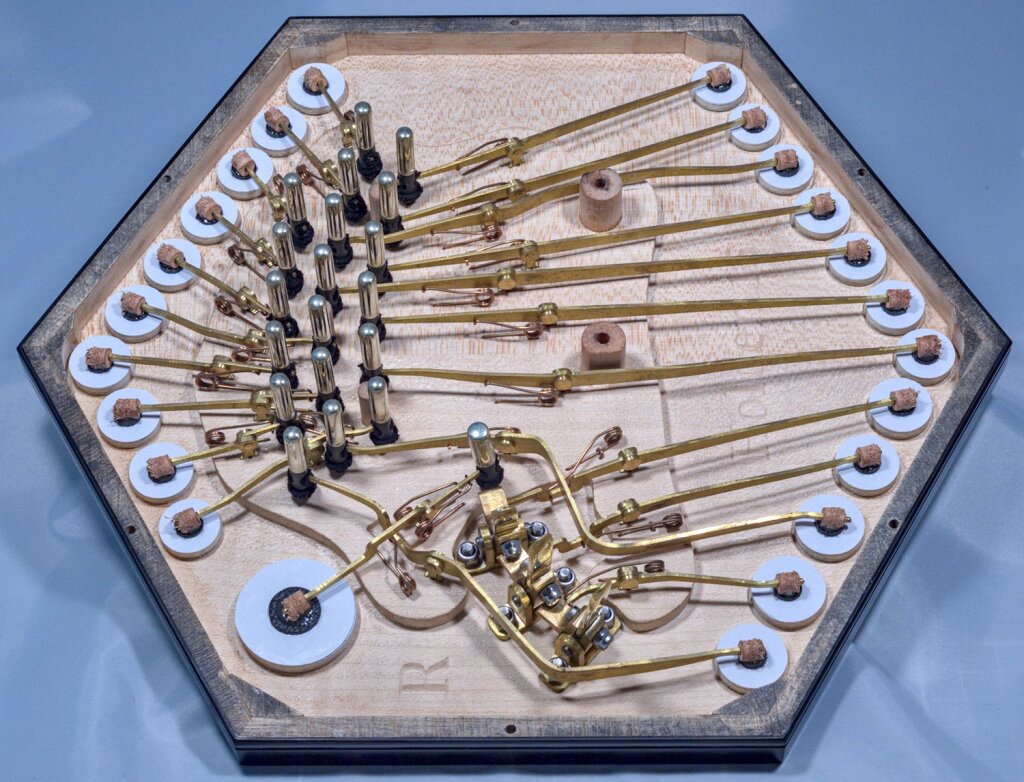
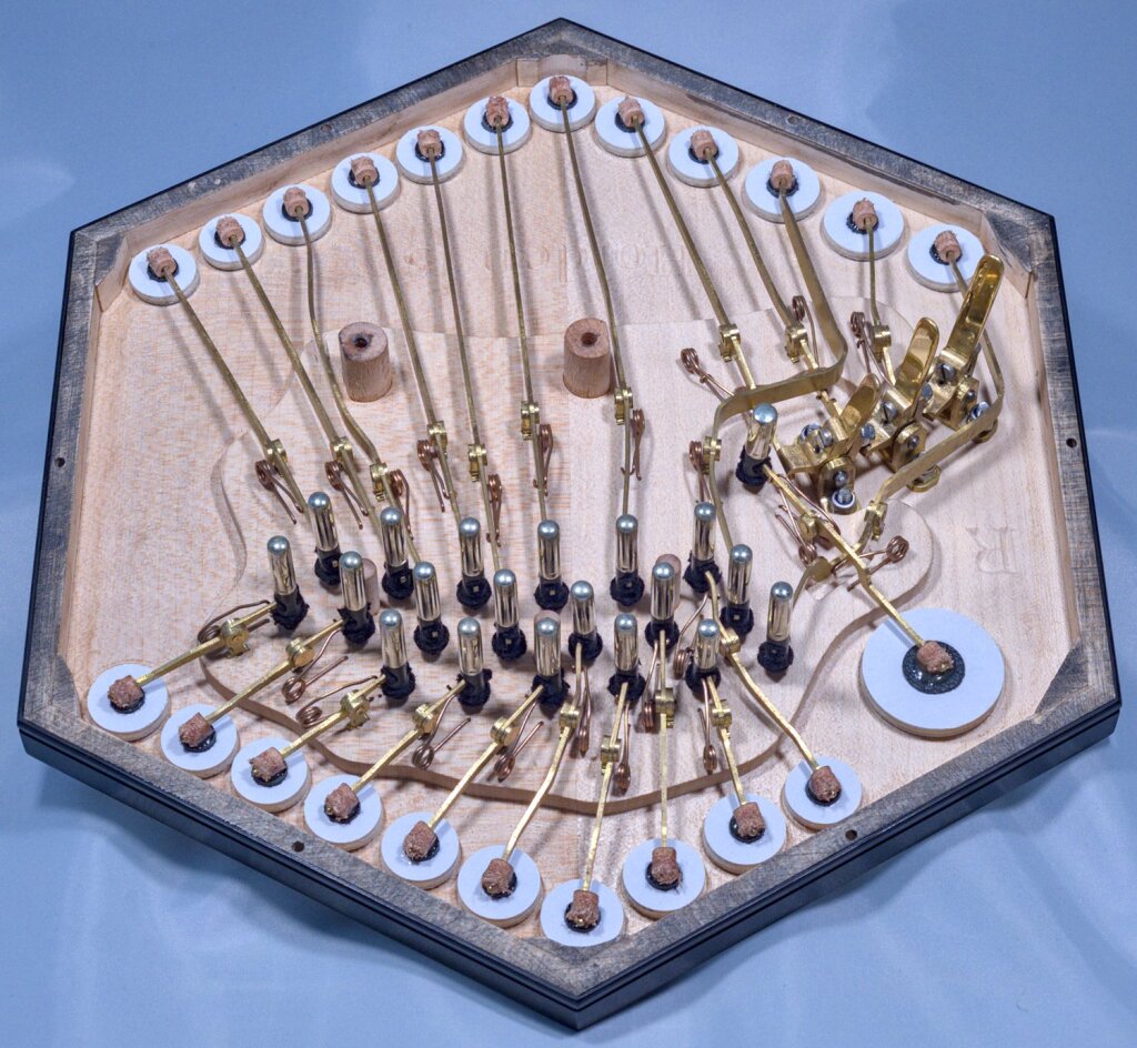
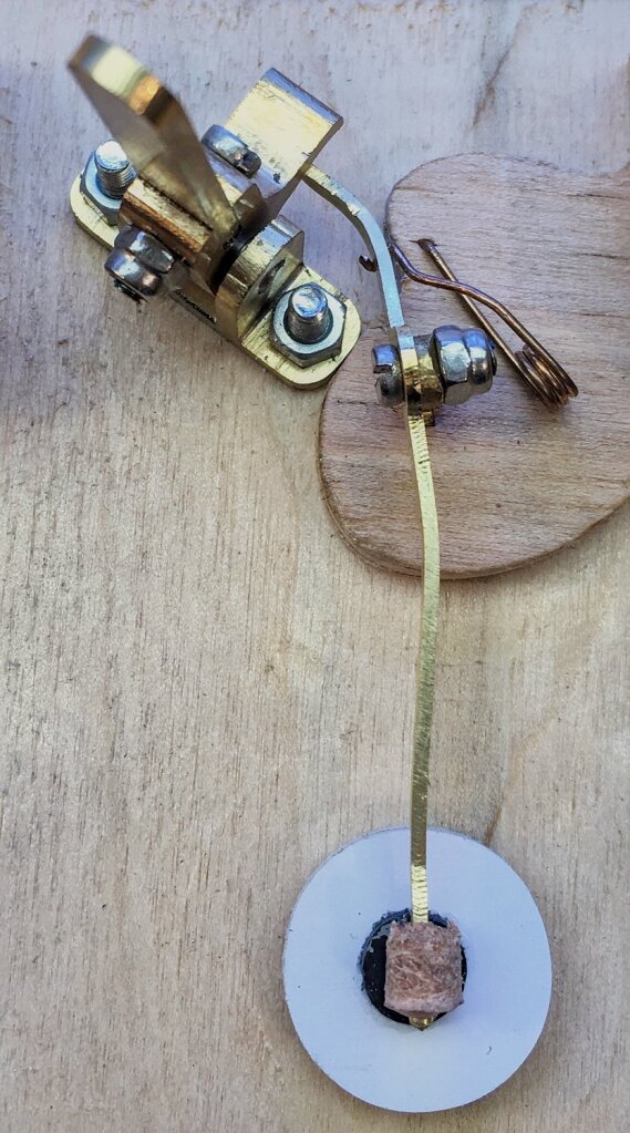
The actions were relatively simple apart from the latchable drone levers and the levers that had to cross over them. I also crossed over the lever for the first button on the middle row so that I could put the largest reed chamber in the middle of the reed pan.
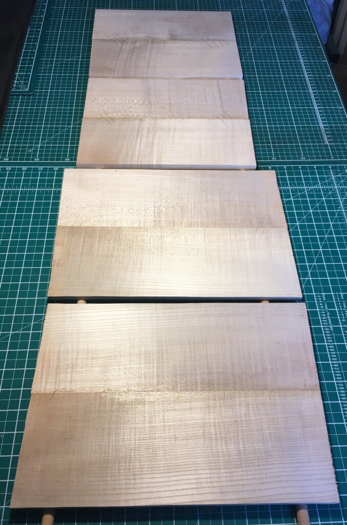
Because this instrument was significantly larger than a standard concertina, the action boards were wider than the solid sycamore boards I have in stock. Even if I had been able to find wider boards I wouldn’t be able to resaw them on my fairly small bandsaw. I solved the problem by jointing two narrower quartersawn boards together. I used the same method for the reed pan boards, so I needed to glue up four wide boards.
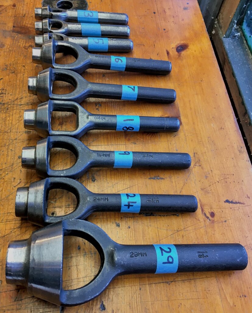
Because bass reeds use quite a bit more air than the lowest reeds in a standard concertina, I added some larger pad sizes to the range that I can make. The lowest note uses a 19mm diameter pad, and I made the air pad 29mm (my standard Anglos have a 24mm air pad).
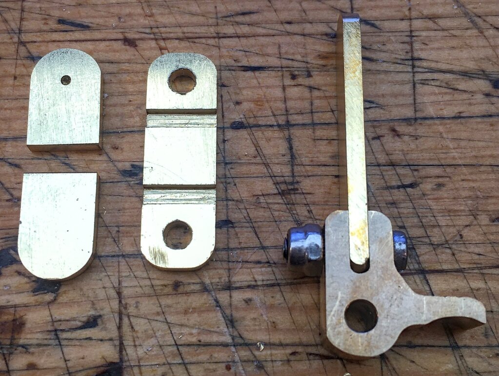
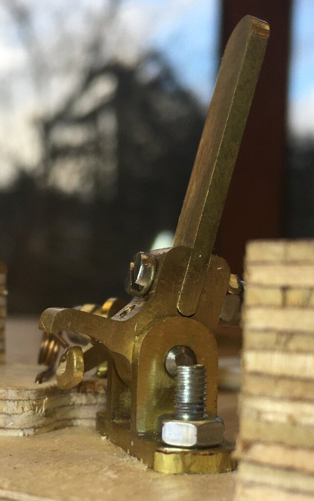
I spent quite a while thinking about the best way to make the latchable thumb levers. They needed to be easy to use, reliable, and not take up too much space. I also wanted to be able to play them momentarily without them automatically latching on. My first idea didn’t work very well – it sometimes got stuck. I refined the idea and built a second prototype, which worked much better.
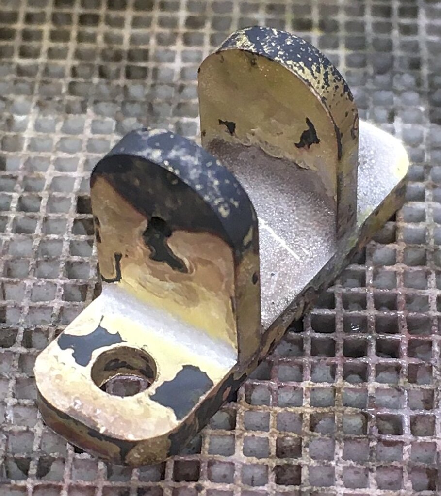
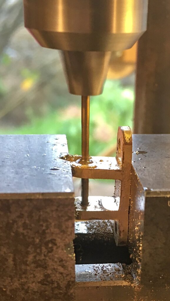
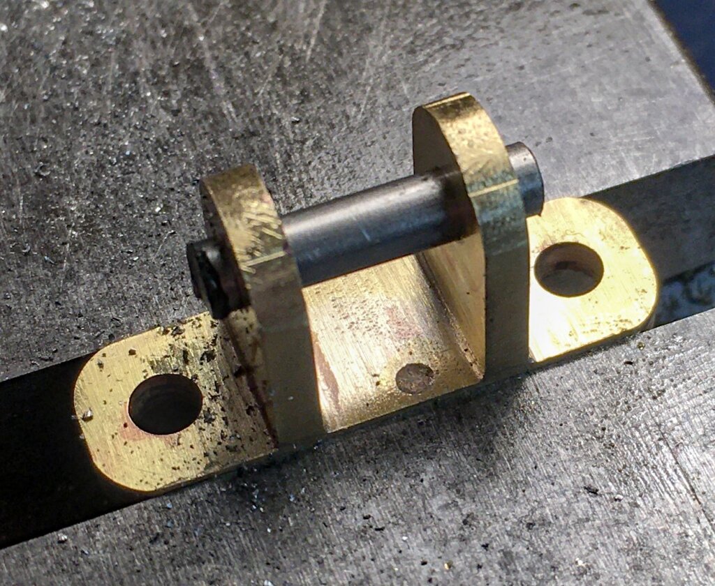
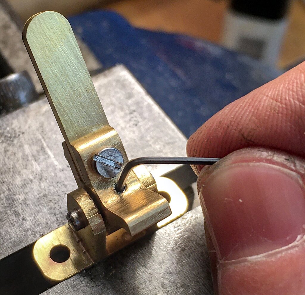
The parts of the thumb lever were mostly milled from flat brass stock, plus a short piece of ground stainless steel rod as an axle, a tiny grub screw, and a stainless screw and lock nut.
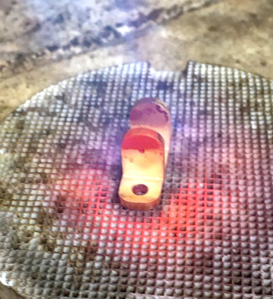
The three parts of the base were silver-soldered together.
The grub screw locks the axle to the centre piece so it can’t fall out.
The screw and nut can be tightened to take out any slop in the fit of the vertical lever.
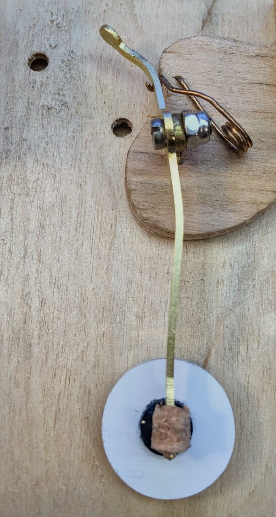
The secondary lever is very similar to a standard button lever except for the shape of the end.
Reed Pans
I developed an improved reed scale for this instrument that has longer reeds in the bass range that are faster, more pitch stable, and have better dynamic range. They also have wider (stiffer) frame sides and larger clamps with four screws instead of two. I also had to figure out new profiles for the bass reeds, using brass weights soldered to the tips at the low end of the range. I thought about using thicker brass plates for the bass frames, but I decided to try sticking to my standard 2mm thickness and they worked out fine.
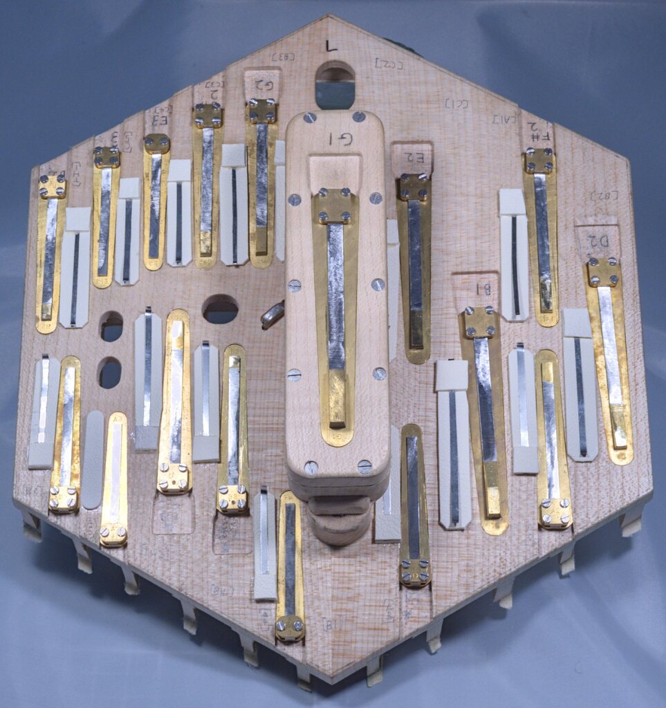
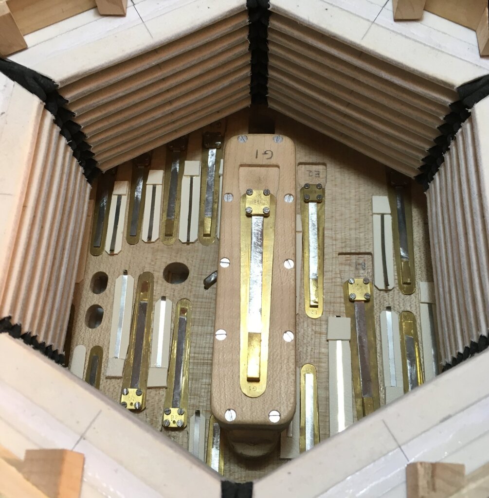
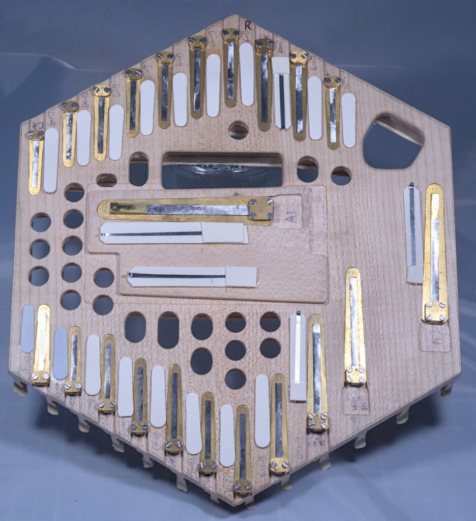
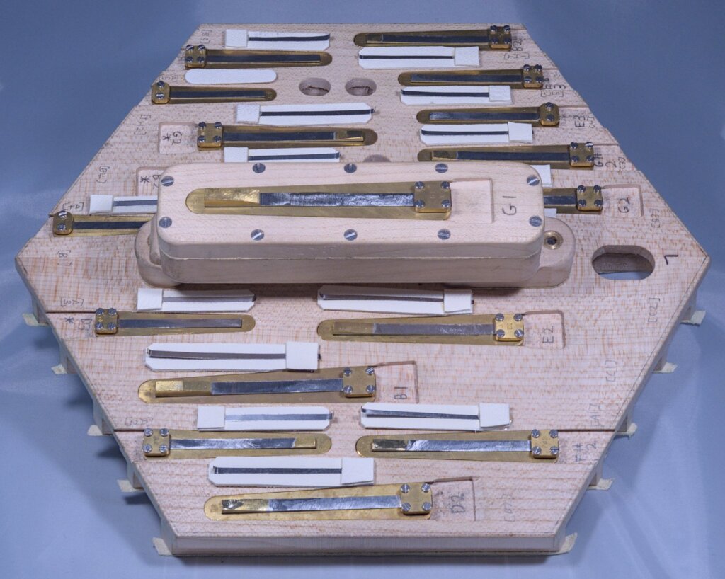
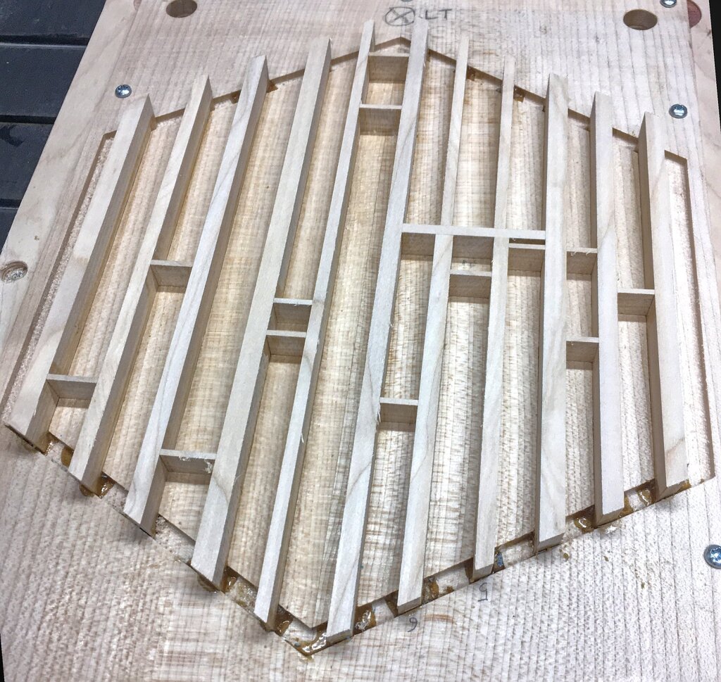
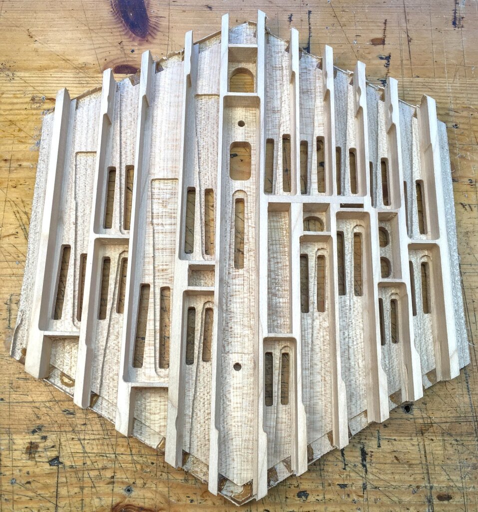
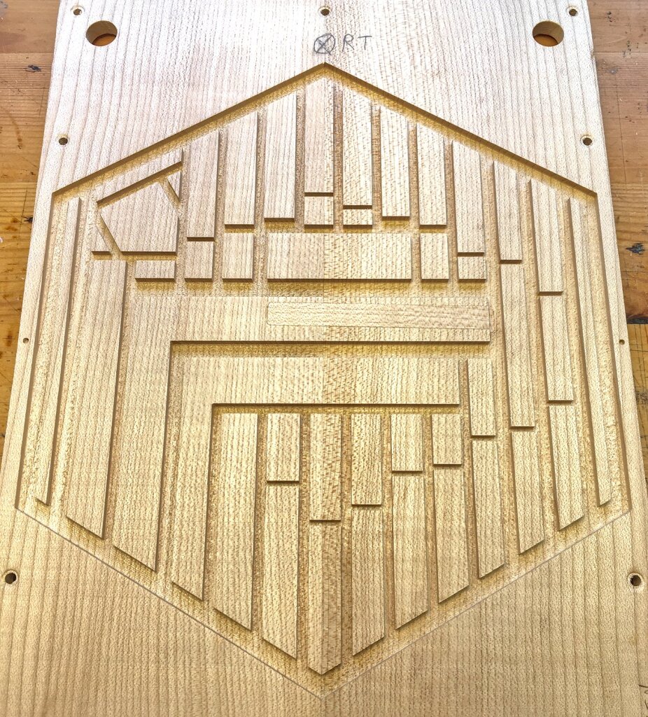
The reed pan design has a few unusual features. The left hand pan is arranged so that the chambers with the lowest reeds in them are as long as possible. This made for some slightly tricky placement of the reeds over on the left side of the pan where some of the chambers extend the full length of the pan.
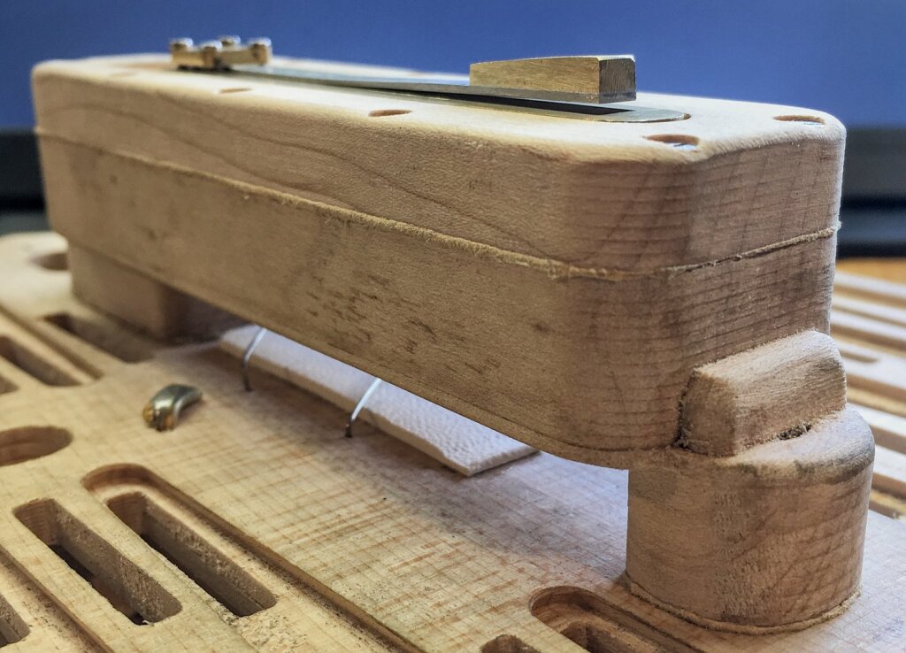
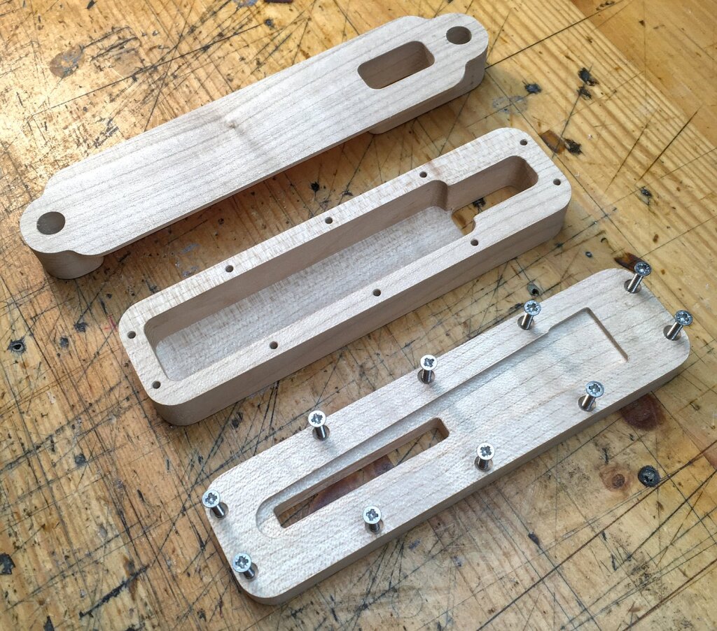
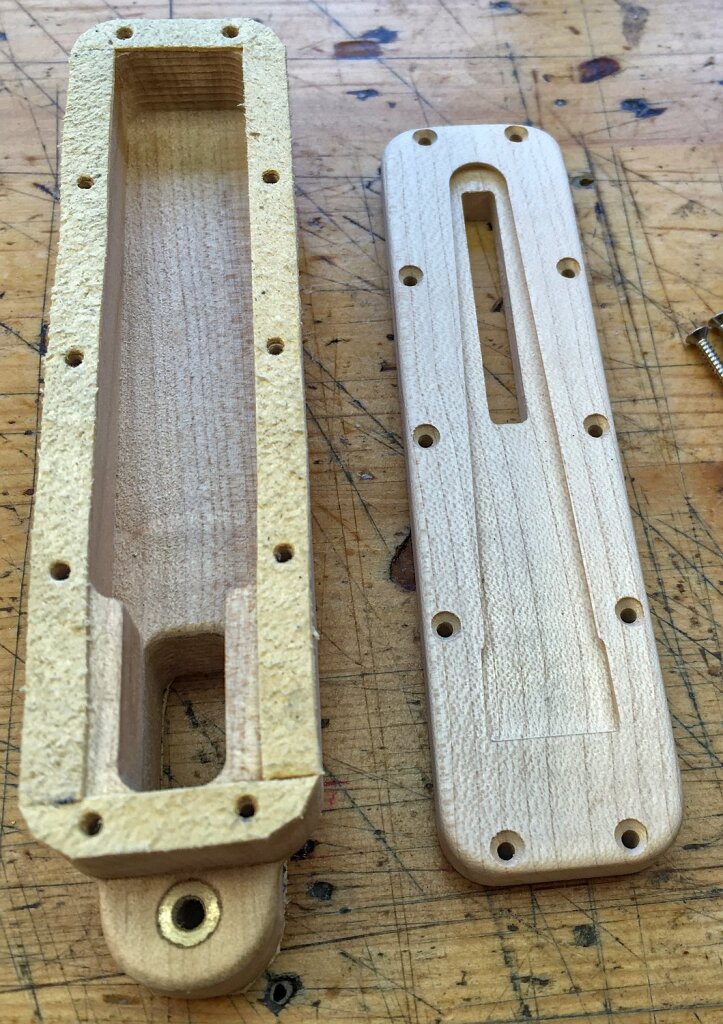
The lowest reed, G1, is in a separate chamber of its own bolted to the bottom of the reed pan. I’ve since seen photos of a 20 button Lachenal bass anglo that has a very similar arrangement for the bottom reed.
The extra chamber is located in the centre of the pan so that it fits into the middle of the bellows. The alternative would have been to make the bellows frame much deeper on the left side.
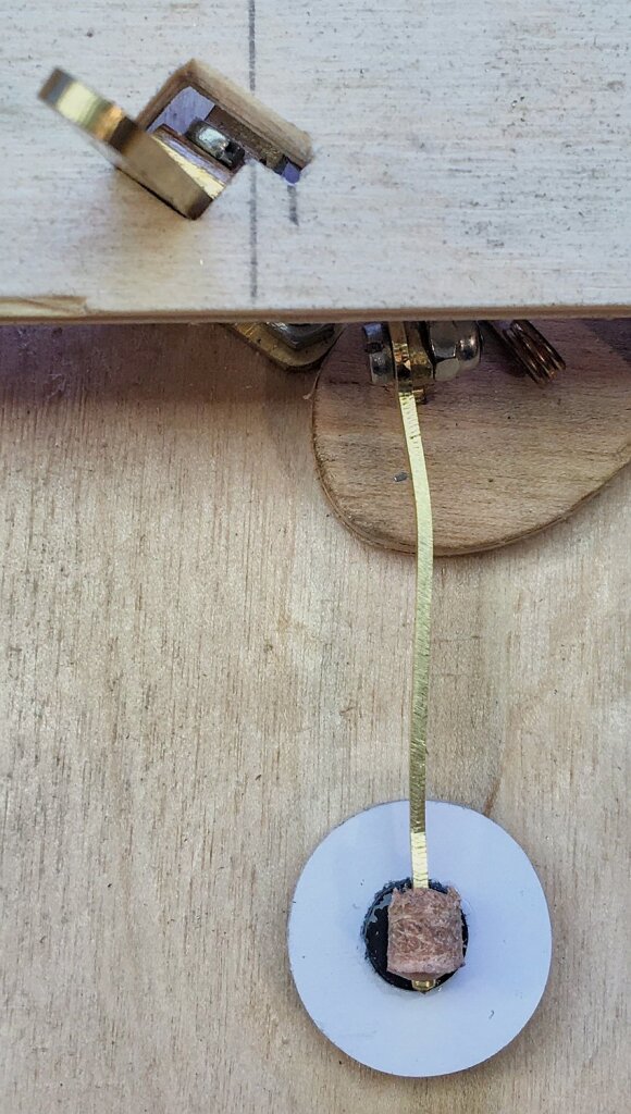
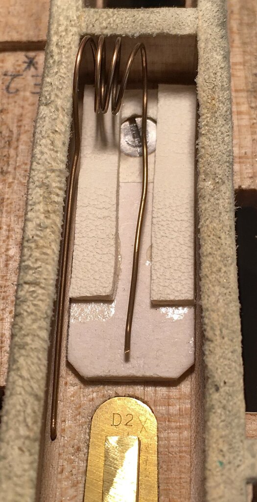
The valve for the G1 reed isn’t where you might expect it to be, inside the secondary reed chamber. Instead I made a special flap valve held closed by a light torsion spring that seals the passageway from the main pan down to the secondary pan. In hindsight, although it worked OK, I might implement the spring a bit differently next time. When I designed it I thought the flap probably wouldn’t need a spring, but I found that it fluttered badly when playing the pull D note until I added the spring.
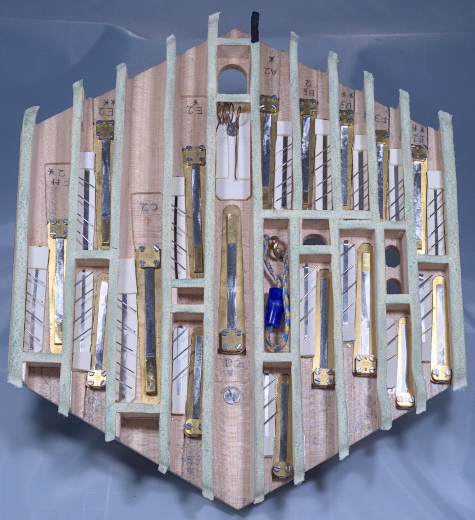
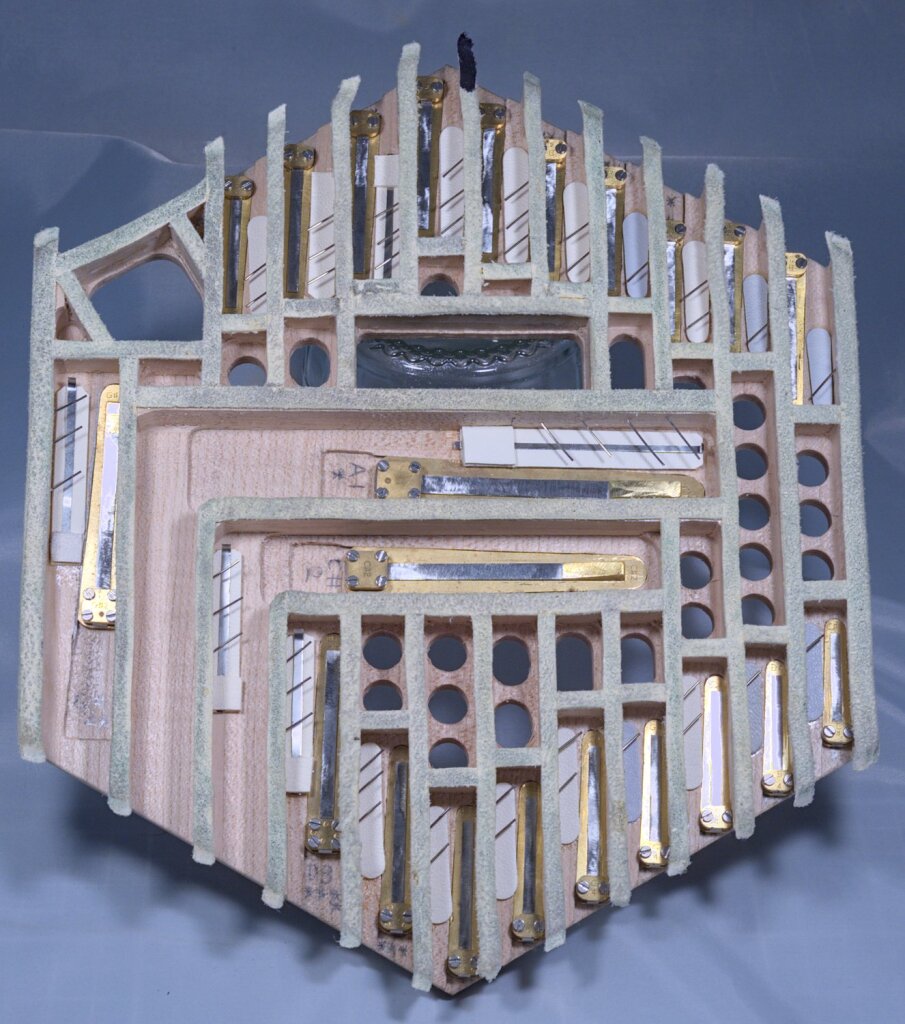
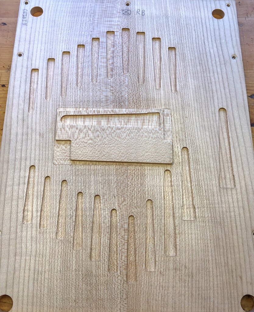
When it came to deciding where to put the drones and extra custom buttons, there was only space for 15 buttons and two drones on the left hand, so we added the rest of them (including some fairly low notes) to the right hand pan. I made it slightly tapered so that the chambers on the left side are deeper than those on the right, and there is an extra deep section in the middle for the A1 drone.
The lower of the two L shaped chambers is an unusual feature: it plays C#3 on the push and C#2 on the pull, with the C#3 reed being in the short arm of the L and the C#2 in the long arm. I wasn’t sure how well that would work but thought it was worth trying the experiment. What I found is that both reeds work OK and the C#2 sounds good, but the C#3 has a ‘woody’ timbre that doesn’t match the reeds around it. I’m not sure if it’s because the chamber has too much volume for the pitch or if it is because the reed tip is located at the corner of the L rather than at the furthest point from the pad hole. Perhaps sound waves are travelling along the long arm to the dead-end and reflecting back to the reed in a way that interferes and alters the sound.
The low A1 drone in centre of the pan works very well and sounds pleasant to my ear, so L shaped chambers aren’t inherently bad.
The large valves for the bass reeds all have accordion-style stainless steel valve assist springs that help the valve to close.
I found the valve assist springs work very well when the spring is sized and adjusted correctly, but there is a bit of a knack to them which took me a few days of experimenting to figure out. I found that it doesn’t work well for the spring to actively push the valve closed (that can muffle the volume or cause it to flutter). Instead the spring should be just barely strong enough to almost close the valve when you hold the pan in its normal playing orientation. Also it’s important that the spring doesn’t have a ‘hump’ shape that pushes down the ends of the valve but not the middle, as that can cause it make an annoying buzzing sound at low volume. Incidentally something I didn’t figure out until later on in the process of learning about valve assist springs is that you probably don’t need any valve restraint pins inside a chamber with a spring-assisted valve, because the spring won’t allow the valve to curl up and get stuck against the roof of the chamber. I thought about taking all the redundant pins out but decided it wouldn’t do any harm to leave them in.
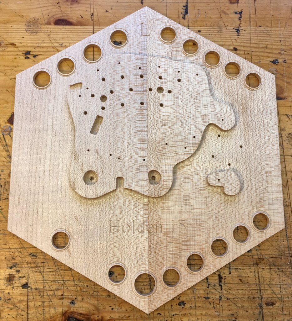
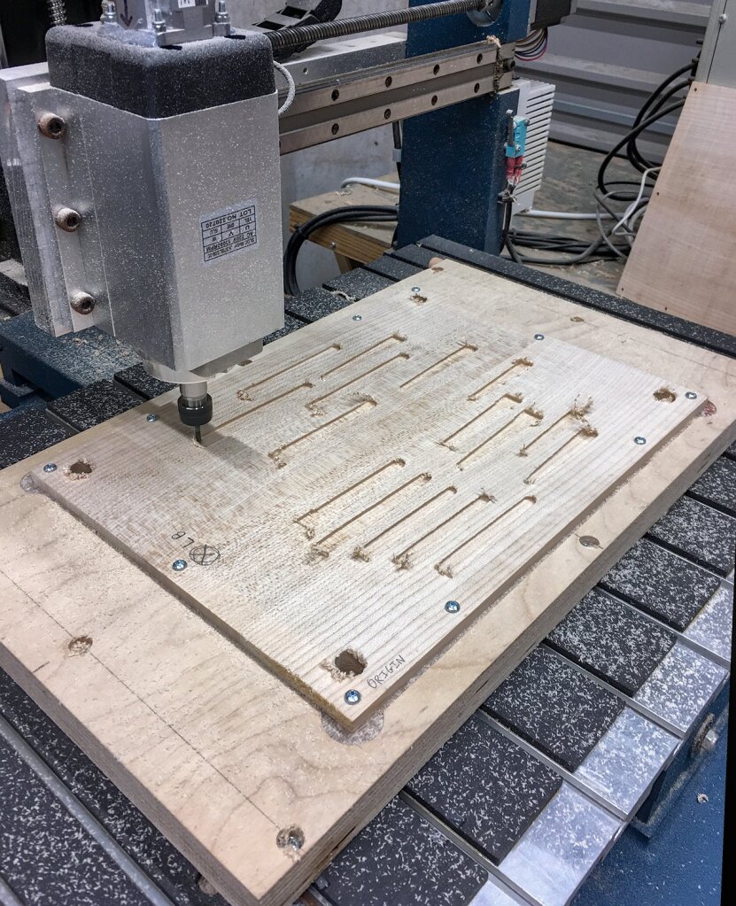
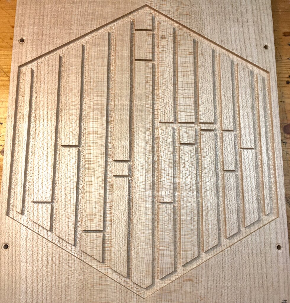
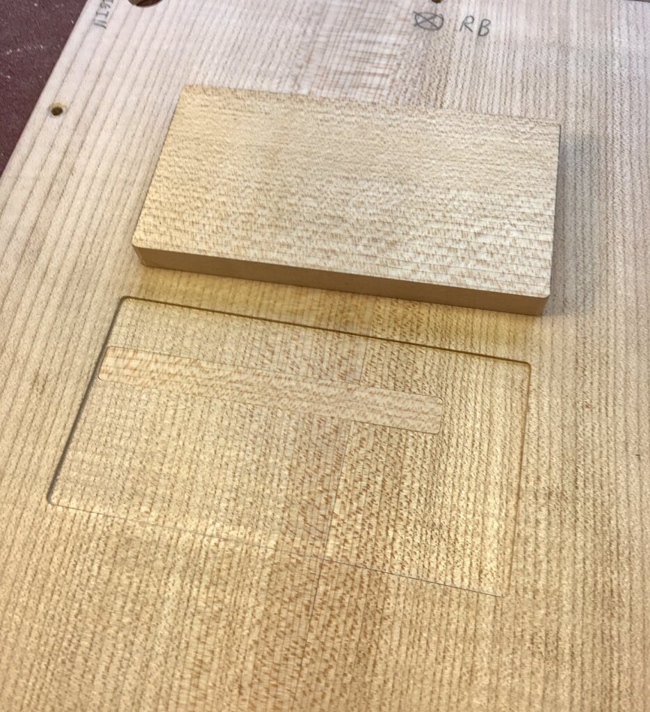
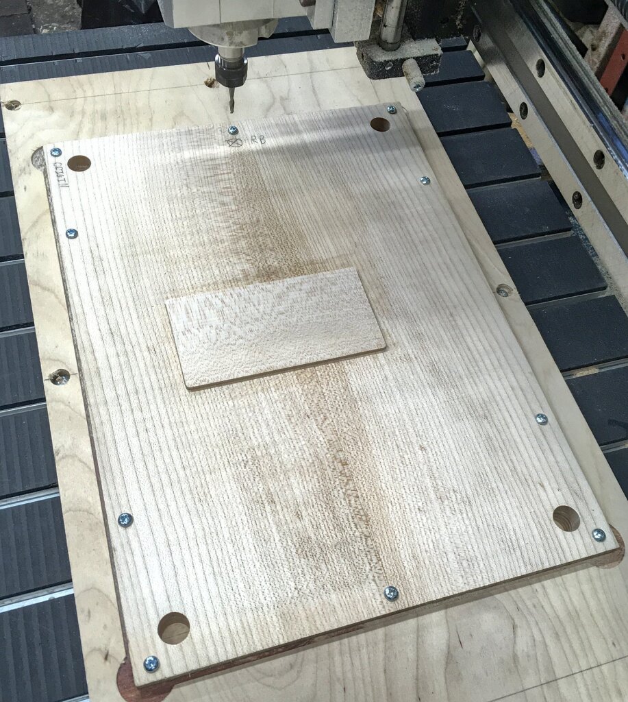
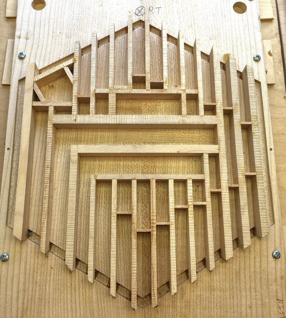
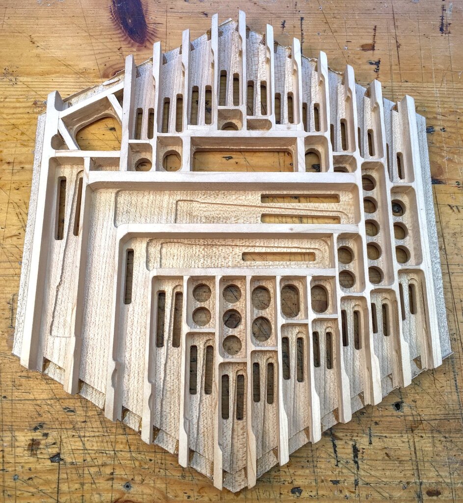
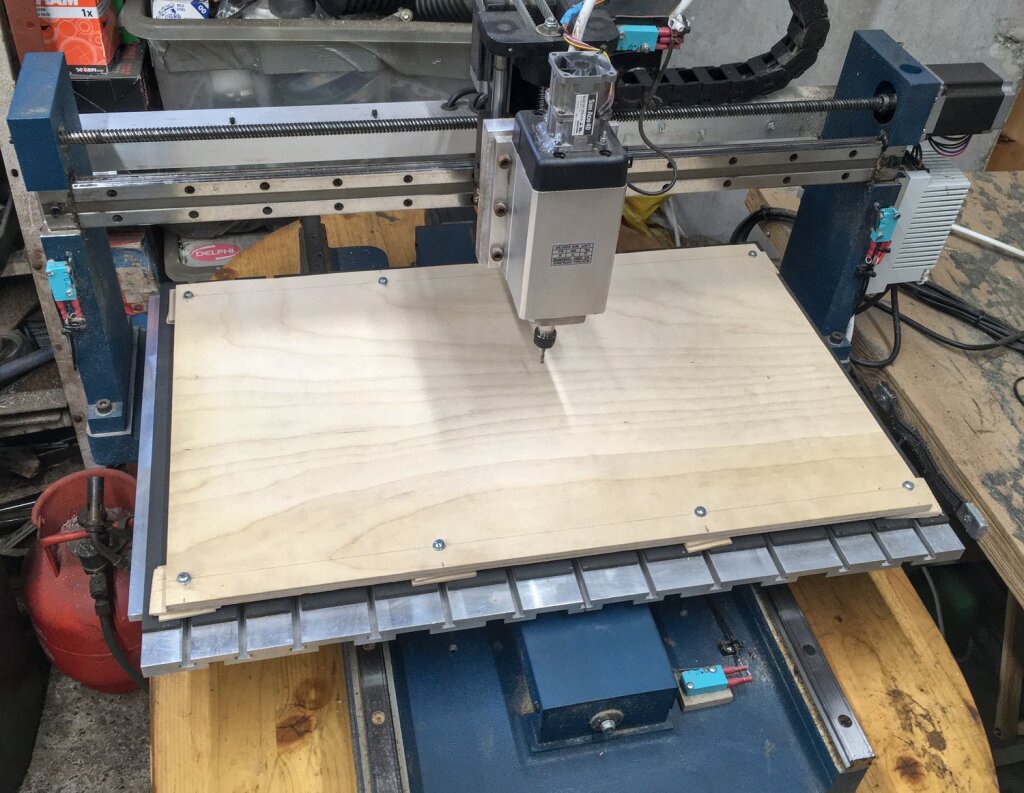
I machined the reed pans on my new CNC router, using a plywood spoilboard with four dowel locating holes in the corners (the same one for both pans).
The add-on reed chamber for the G1 reed was made from three layers of sycamore: the base/standoff that had an air channel and space underneath it for the pull reed’s valve, the bottom half of the chamber that was glued to the base, and the top half of the chamber that was screwed on with a chamois gasket between the two halves, in case I ever need to get to the inside of the chamber for cleaning or something. In hindsight the screws were probably unnecessary and I could have got away with gluing the lid on.
I considered making the reed frame screw to the face of the chamber rather than a friction fit into a dovetail slot, but I have found in the past that screwed reed assemblies can sometimes be a bit fussy (e.g. the tuning changes depending on how tight the screws are).
Similar to No. 13, the right hand pan had an extra piece of sycamore glued to the middle of the bottom side with the grain running at 90° to the main board. This allowed the two chambers in the middle of the pan to be routed deeper than the others. I also installed a narrow inlay piece to reinforce the section between the two A1 reeds.
Bellows
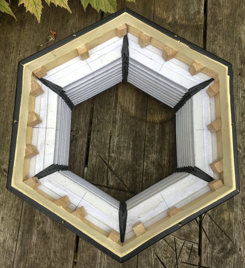
The bellows frames needed to be deeper to allow space for the bass reed chambers, so I increased the number of splines reinforcing the joints.
I continue to refine my bellows-making processes and these are probably the best bellows I have made so far. They have a huge lung capacity and I suspect seven folds would have been plenty, but we decided to go with eight just in case the extra capacity was needed when playing the bass reeds loud.
Case
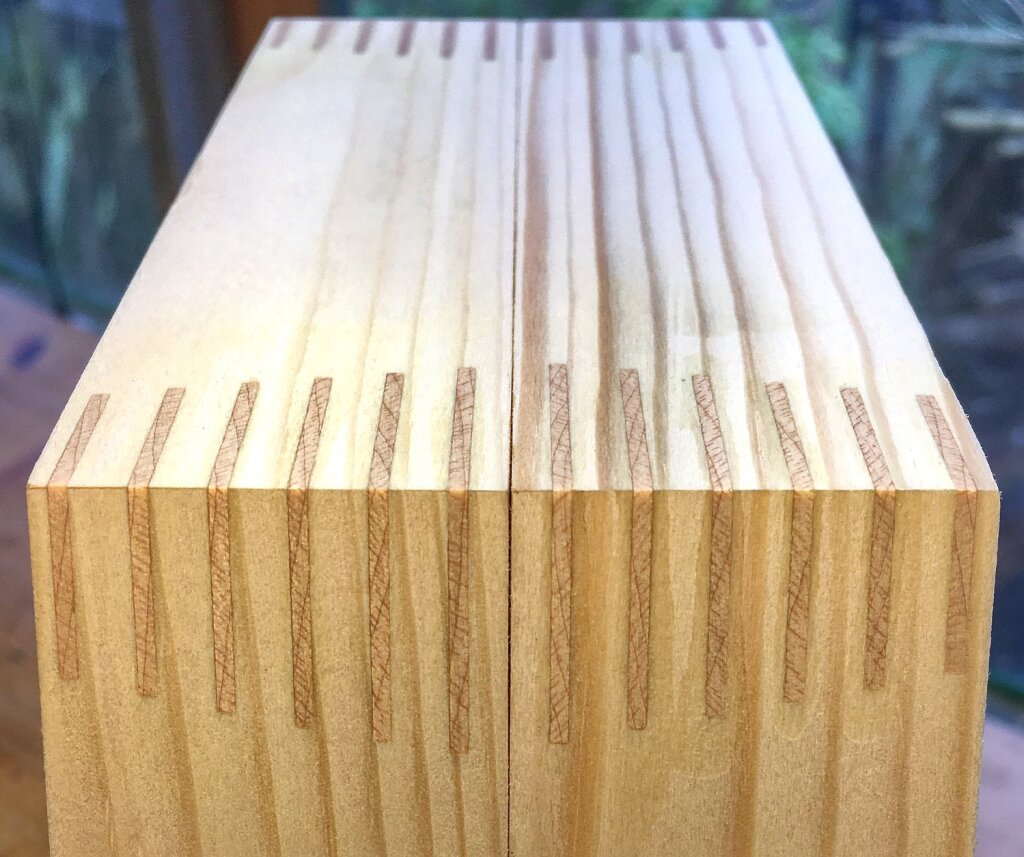
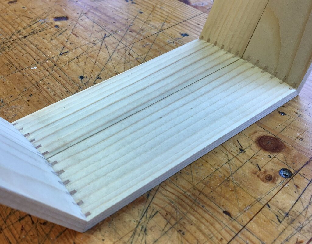
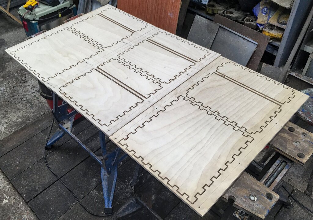
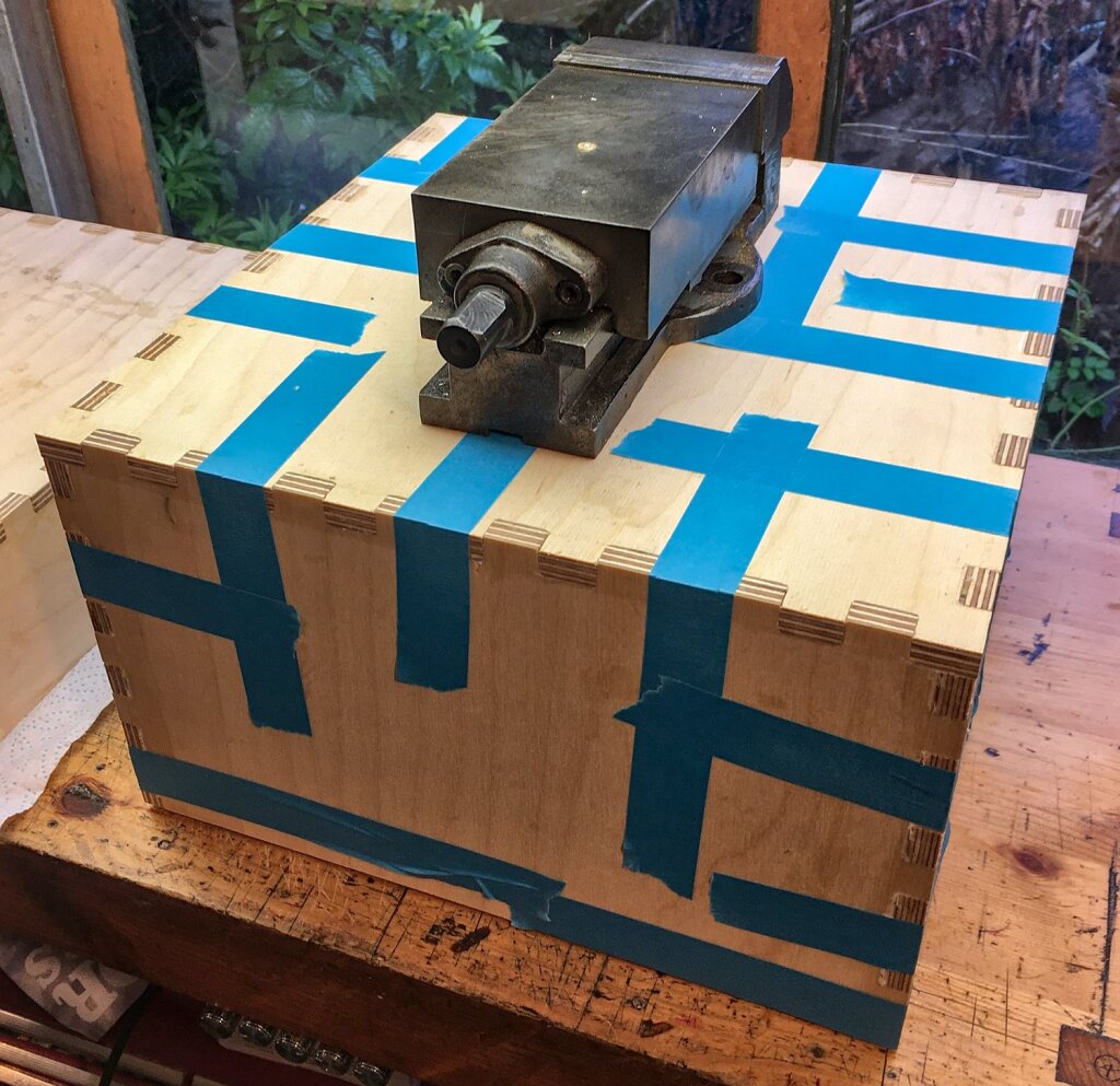
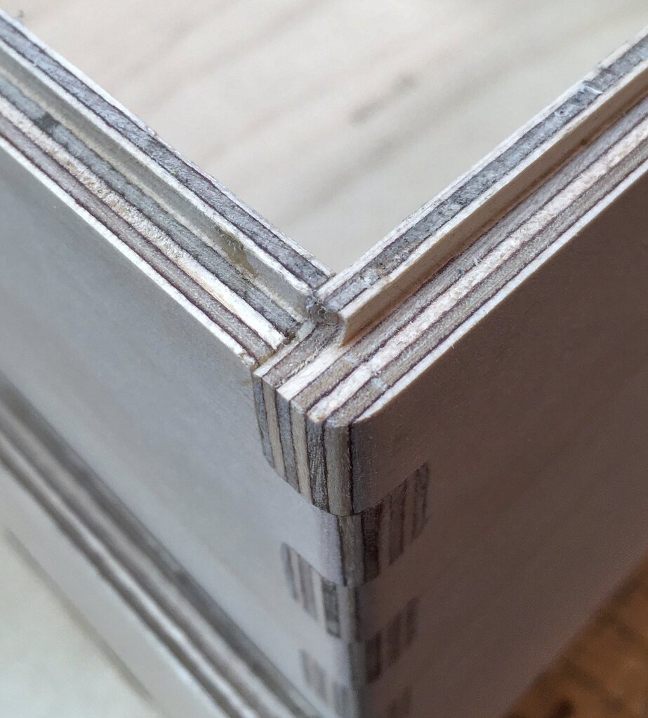
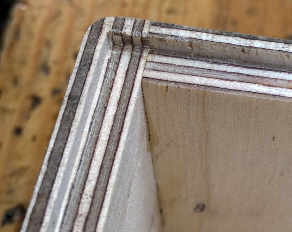
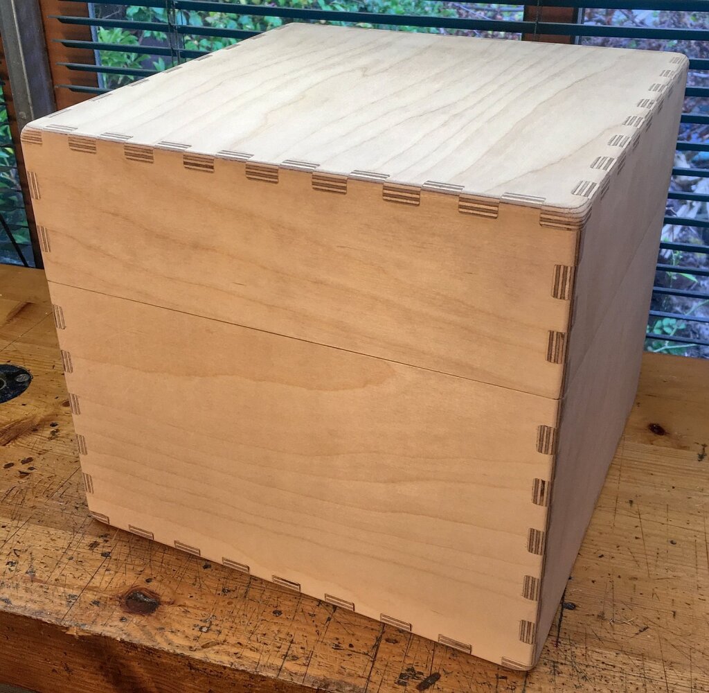
The deluxe hard case was fairly similar to the ones I have made a few times previously, e.g. for No. 9. The main difference was that I cut the walls on the CNC router, with simple finger joints rather than hand-cut dovetails. The resulting joints should be plenty strong enough while being a fair bit quicker to make and fit together more accurately. I also cut the lip for the weather seal as part of the process. Now that I have made one box this way, it should be pretty easy to scale the design up or down a bit to make cases for different sizes of instrument. Unfortunately good quality birch plywood is so expensive now that the wood alone costs more than I used to pay for a standard budget Italian case, never mind decent fittings, covering/lining materials, and several days of labour. It doesn’t really make much economic sense for me to sell these cases, but it’s nice to be able to offer a higher quality option to my customers.
Incidentally this is the first full instrument I built with my new-to-me CNC router. It’s actually a lightly used 20 year old industrial engraving machine with ball screws and linear rails, but I have replaced the spindle, stepper motors, limit switches, and all the electronics. I would have struggled to have made the wooden parts for such a large instrument on my old CNC mini mill. As well as having a much larger work volume it is significantly faster, while still being pretty accurate and rigid enough for the sort of work I do. In the future I will probably use the new router for all of my wood routing tasks (even on small instruments), while continuing to use the mill for most of the metal parts like action levers and reed frames. One problem I haven’t yet solved is a proper permanent location for it and a sturdier stand that doesn’t wobble around when the table does rapid movements.
