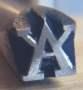
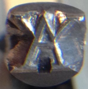
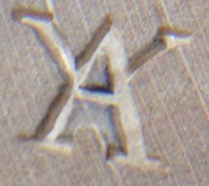
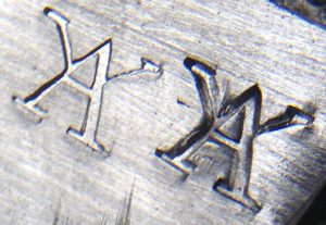
Hand-Cut Maker’s Mark Punch
There is something magical about the ability to anneal1 high-carbon steel, work it into a useful tool, then harden and temper it so that it can hold a sharp cutting edge for a long time. It was one of the most important discoveries of the Iron Age, enabling the manufacture of tools that were far superior to those made of softer metals like copper, bronze and wrought iron.
I have made a few hardened steel tools of my own; wood carving knives and gouges, and simple punches. It is a wonderful and exciting feeling to use a tool that you made yourself.
Part of the process of hardening tool-steel involves heating it to something in the region of 760-800C2 and holding it at that temperature for a while. If the temperature is too low the steel won’t harden properly, and if it’s much too high you get a coarse grain forming inside the metal that will affect your ability to sharpen the tool. In the past I’ve heated my tools using either an open solid-fuel forge or a propane blowtorch, but in both cases it is difficult to accurately gauge and regulate the temperature. Because I need to make more tools for concertina production (mainly press dies), I’ve been looking out for a better way to heat them.
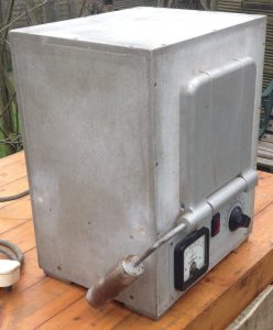
Recently I came across an old electric laboratory muffle furnace on eBay. Luckily I managed to get it very cheaply because it was described as faulty and it was near enough for me to collect it in person. It looked to be in good condition in the photos, and I figured that even if the heating element had burned out, it would be cheaper and easier to re-wind it than to build one from scratch.
The fault turned out to be very simple. It is supposed to have a fusible link inside the inner chamber that melts if you overheat it (a thermal fuse). This was probably quite easy to do because the original controller was a simple simmerstat3, and I suspect leaving it at 100% would cause it to reach melting point in about 45 minutes. The thermal fuse was missing. As a temporary measure I bypassed it and the oven fired straight up.
I learned nearly everything I know about heat-treatment of steel from Hardening, Tempering & Heat Treatment by Tubal Cain from the Model Engineer’s Workshop Practice series. It was only after I’d bought my oven that I happened to be flicking through the book and saw a picture of it: the author had the same model!
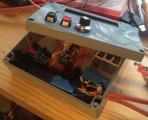
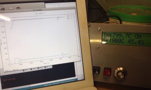
Tubal Cain had replaced the simmerstat in his heat treatment oven with an early computerised temperature controller. I wanted to do the same thing, and I could have simply bought a fairly cheap Chinese PID controller like the one I used on my glue pot (though high-temperature ones seem a bit harder to find and more expensive), but for various reasons I decided to build my own instead. I used a MAX31855 thermocouple interface from Adafruit, an Arduino Nano clone, a solid state relay, a 16×2 alphanumeric LCD (HD44780 compatible), a couple of push buttons and a rotary encoder stuffed into a plastic project box. Because I already had most of the parts other than the high-temperature K-type thermocouple (which I would have had to buy anyway) and the MAX31855, the project worked out pretty cheap.
I developed the firmware using the Arduino IDE and several off-the-shelf open source libraries. This is the first time I’ve used the Arduino system, though I’ve done quite a bit of embedded programming in the past. I must admit a decent C++ compiler and a large set of libraries made it pretty easy to quickly bolt something together, though the lack of a debugger is a bit of a pain, and some of the libraries are poorly documented and/or provided with example code that doesn’t work properly out of the box.
The most difficult part of the project turned out to be tuning the PID loop parameters. Get them wrong and the oven either never reaches the desired setpoint or it overshoots and oscillates around the setpoint. One advantage of developing my own Arduino-based controller was that it was easy to log the temperatures and power level at regular intervals to a laptop over USB, then plot a graph to figure out what was happening over time. To cut a long story short, after hours of test cycles and trying many different values, I eventually found a set of parameters that perform well enough for my purposes. It overshoots by a few degrees when it first gets up to temperature or after disturbing the system by opening the door, but I don’t believe that is enough to cause a problem. In this graph, the blip at 5200 seconds is the result of me opening the door for a few seconds:
For years I have been fascinated by how punches and dies were made prior to the invention of the rotary engraving machine. I’ve read what I’ve been able to find on the subject (not very much, to be honest) and studied some antique punches to try to work out how they were made. I decided to try making a punch from my maker’s mark to see if my ideas were practical.
I think positive punches and single-line name stamps usually used at least one counterpunch per letter to form the hollow spaces (the counters), and the outside waste was cut away with saws, files and probably a selection of gravers. There were also negative punches that were probably either entirely engraved or stamped with a set of reversed positive punches, but I’m not going to cover those today.
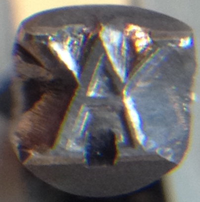
My maker’s mark is a fairly simple symbol (an upper case A with two arms added), though I wanted to challenge myself by making a serif version with multiple stroke widths.
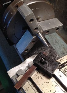
I made both the counterpunch and the punch from 3/8″ silver steel, which is a commonly-available high-carbon water-quenched tool steel with a little chromium in it that is supplied as accurately ground round bar. Since the counterpunch was to be smaller than the punch I first tapered the end. There are several ways to do this, but I decided to use the compound slide on my Taig lathe. I also used the lathe to face both ends to make them square, and used a file to round over the hammer ends a little so that when you strike it you don’t hit a corner.
The facing process left the end that was to become the punch square and reasonably flat but very slightly rough. Because this might effect the performance of the finished punch I decided to lap it flat.
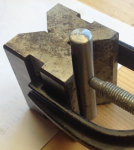
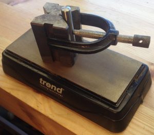
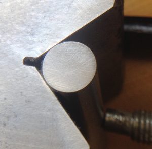
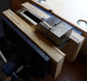
First I clamped the blank in a Vee block, using a piece of paper as a shim to make sure the punch protruded from the block by a tiny amount:
Then I lapped it on a cheap diamond plate in a figure-eight pattern:
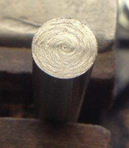
The lapped face of the punch blank:
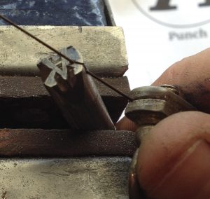
Next I started cutting the counterpunch using a jeweller’s saw to make the initial grooves:
I removed the waste from the outside using a fine flat hand file:
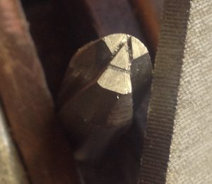
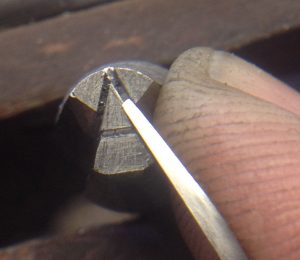
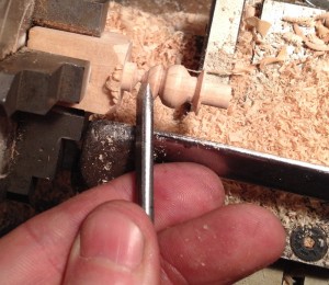
Then I used a graver to widen the grooves (you can see in this one it’s pretty small compared to my index finger):
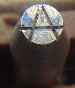
The nearly-finished counterpunch:
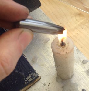
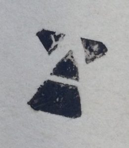
To check it was the right shape, I got it sooty in a candle flame and pressed it onto a piece of paper (this is called a smoke proof). Actually I realised at this stage that I had made a mistake, but I opted to push ahead and modify the proportions of the punch to compensate rather than starting again. I could get away with this because the design of my mark is rather fluid anyway, and doesn’t have to match the style of a particular font.
The final part of cutting the counterpunch was to bevel the corners and do a test punch into a piece of end-grain hardwood. I’ve found that a punch doesn’t work very well if you don’t bevel it at all, but it’s not entirely clear to me how steep the bevel angle should be (the old punches I’ve looked at aren’t all the same).
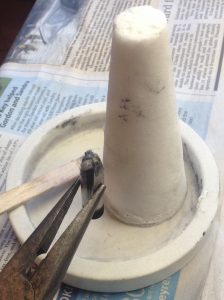
Next I had to harden the counterpunch before I could use it. In order to reduce scale buildup and decarburising while soaking in the heat treat oven, I coat the business end of the tool in jeweller’s borax flux. Applying it isn’t an exact science. I warm the punch to not-quite boiling point, then smear some thick borax paste onto it and wait for it to dry. Once in the oven, it will bubble up a bit at first but then it should melt and flow out across the surface (you can see the difference after heat-treating; the areas that were protected by the flux are still bright underneath).
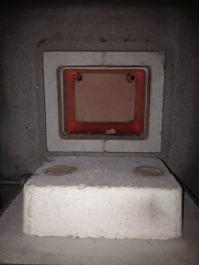
I put the counterpunch into the oven on top of a piece of bent stainless steel that prevents it directly touching the oven floor. After waiting something like 20 minutes for it to get up to temperature, I let it soak for another 20 to ensure that it was fully austenized all the way through. From what I’ve read, not soaking for long enough will significantly reduce the hardness you can achieve.
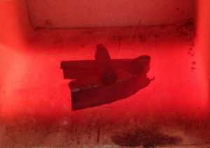
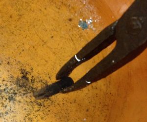
After soaking, I pulled it out with blacksmith’s tongs and immediately quenched it in a bucket of water. The shock actually causes most of the Borax flux to fall off, which is handy because it can be difficult to remove.
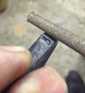
As a quick check to make sure it hardened, I see if a file will cut it. Generally it will scratch a tiny bit because of the surface decarburisation effect but it will be hard enough underneath that the file just skates off. Some people recommend using a good sharp file for this test, but I find that it tends to blunt the file so I prefer using a rubbish file and just press quite hard (I have experienced a tool that didn’t harden properly and the difference was pretty obvious).
After hardening, the steel is very hard but also very brittle and highly stressed. If you’re not careful you can shatter it just by rough handling (I’ve done that with a fancy spring clip that I had just spent half an hour forging). What we do to cure this is to temper it, which means re-heating it to a lower temperature and soaking it for a while. This reduces the hardness somewhat but also reduces the internal stress and greatly increases the toughness of the steel. If you temper it lightly you end up with quite a hard tool that might be at risk of chipping. Higher tempering yields a tougher but softer tool; if you go too far the edge may tend to roll over in use. The highest levels of tempering are used to make springs.
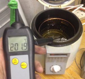
There are several ways to heat a tool for tempering. I could even use the heat treat oven itself, but it would take a few hours to cool down sufficiently and it’s not a good idea to leave the tool in its fully hard state for that long. I decided to use a small electric deep fat fryer with sunflower oil in it. The highest temperature the thermostat will go up to is about 200C (and the oil probably wouldn’t be happy going much higher than that), which is towards the low end for tempering silver steel.
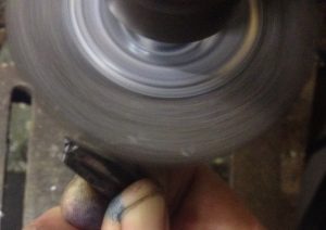
After tempering I used a rotary wire brush in the pillar drill to remove the scale and any remaining flux.
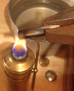
Finally I used a spirit burner to re-heat the blunt end up to a spring temper so that it can better resist the shock of hitting it with a hammer. It will probably mushroom eventually but it is easy to cure that by grinding. After it reached a blue colour I quenched it again to stop the heat travelling too far up the shank.
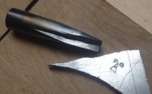
A quick test in a piece of scrap aluminium proved it had worked as planned:
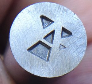
The first stage of cutting the real punch was to strike the counterpunch into it. I think this is possibly the most difficult part of the entire process. You have to line it up perfectly, then hit it multiple times very hard to drive it as deeply as possible into the steel. Although the silver steel is supplied annealed, it is still a pretty tough material and it takes a lot of force to counterpunch it. The counterpunch bounces out of the indentations after every strike and you have to be very careful to line it back up perfectly before the next strike – I had a bit of an accident and made an extra small dent but luckily it was in a waste area. The counterpunching causes the surface to raise up a bit around each indentation, which I opted to get rid of by lapping it flat again. Here is the result after counterpunching and lapping:
I roughly removed the majority of the waste from the outside with a jeweller’s saw and files again:
Mostly done, though not yet adjusted the width of the strokes:
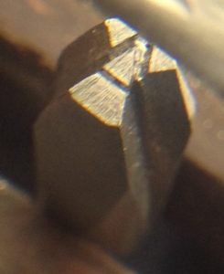
After a bit more fine fettling, and adding the bevels:
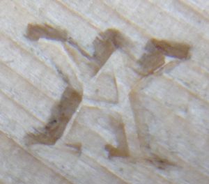
I didn’t bother photographing the hardening process as it was exactly the same as for the counterpunch. The final set of photos shows the result of testing it in several different materials. First end-grain beech:
Aluminium, both a light strike and a heavy one:
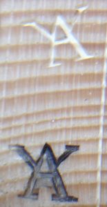
A light strike into side-grain pine tended to crush the soft fibres:
End-grain pine worked fairly well though. The bottom one was an experiment in soot blackening the punch first:
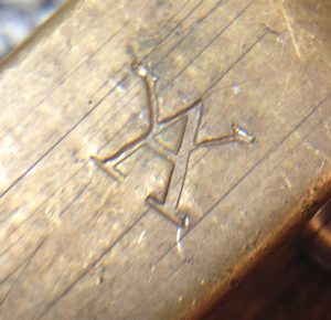
Brass. I had to hit it pretty hard to get a decent impression but it came out quite nicely:
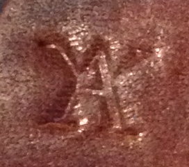
Thick leather. This looks sharper in reality than the photo appears to show:
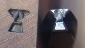
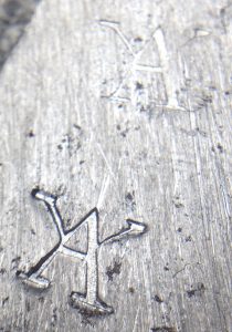
Mild steel. The top mark was a moderately hard strike onto the wooden bench and it’s barely visible. The bottom mark was a very hard strike backed by a steel anvil. I’m not sure I’d want to risk striking the punch that hard very often as I’m concerned the tiny serifs might be at risk of breaking off, though it didn’t suffer any visible damage as a result.
