Search Results for: 2V0-62.23 Schulungsangebot, 2V0-62.23 Testing Engine, VMware Workspace ONE 22.X Professional Trainingsunterlagen 🐟 Öffnen Sie ⮆ www.itzert.com ⮄ geben Sie ➽ 2V0-62.23 🢪 ein und erhalten Sie den kostenlosen Download 🌮2V0-62.23 Testengine

Steppers

The stepper motors have arrived that I’m going to use to convert my Taig Micro-Mill to CNC.

steppers

It’s hard to explain how exciting this is. I’ve dreamed of owning a CNC machine tool for probably twenty years and yet somehow never got around to building one. I bought the Taig about a decade ago for another project with the intention of fitting it with DC motors and encoders and building my own servo controllers (in hindsight that was a bit of a silly idea considering steppers are relatively cheap and work OK on a machine as small as the Taig). I got as far as buying the motors, encoders, pulleys and toothed belts, and a large block of aluminium that I was going to machine the mountings from, before the project ground to a halt. There are some photos on my old website of the mill when I first received it. I have used it occasionally as a manual mill but what I really want is to be able to use it to machine complicated parts under automatic control.

The motors are bigger than I expected, and I went for the small end of the range people tend to put on this machine. There are a couple of different theories on stepper motor sizing for the Taig mill: 1. use small motors and keep everything well adjusted and lubricated so you don’t need lots of torque. 2. use big motors so you have lots of torque in reserve and it doesn’t matter so much if the leadscrews and slides get a bit stiff. The advantage of the smaller motor option, as well as lower cost (both in terms of the motors and the electronics to drive them), weight, power consumption, and heat generated, is that smaller motors have lower winding inductance and armature mass. Lower inductance means the torque doesn’t drop off as rapidly as the speed increases; lower mass means they can accelerate and decelerate quicker. I’ve read people advocating both paths and claiming to get better results with small/large stepper motors, but the smaller, nimbler option appealed to my sensibilities more (as somebody who is happy driving a small, light car with a 48Bhp engine).


Hand-Cut Maker’s Mark Punch

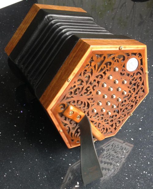
There is something magical about the ability to anneal1 high-carbon steel, work it into a useful tool, then harden and temper it so that it can hold a sharp cutting edge for a long time. It was one of the most important discoveries of the Iron Age, enabling the manufacture of tools that were far superior to those made of softer metals like copper, bronze and wrought iron.

I have made a few hardened steel tools of my own; wood carving knives and gouges, and simple punches. It is a wonderful and exciting feeling to use a tool that you made yourself.

Part of the process of hardening tool-steel involves heating it to something in the region of 760-800C2 and holding it at that temperature for a while. If the temperature is too low the steel won’t harden properly, and if it’s much too high you get a coarse grain forming inside the metal that will affect your ability to sharpen the tool. In the past I’ve heated my tools using either an open solid-fuel forge or a propane blowtorch, but in both cases it is difficult to accurately gauge and regulate the temperature. Because I need to make more tools for concertina production (mainly press dies), I’ve been looking out for a better way to heat them.

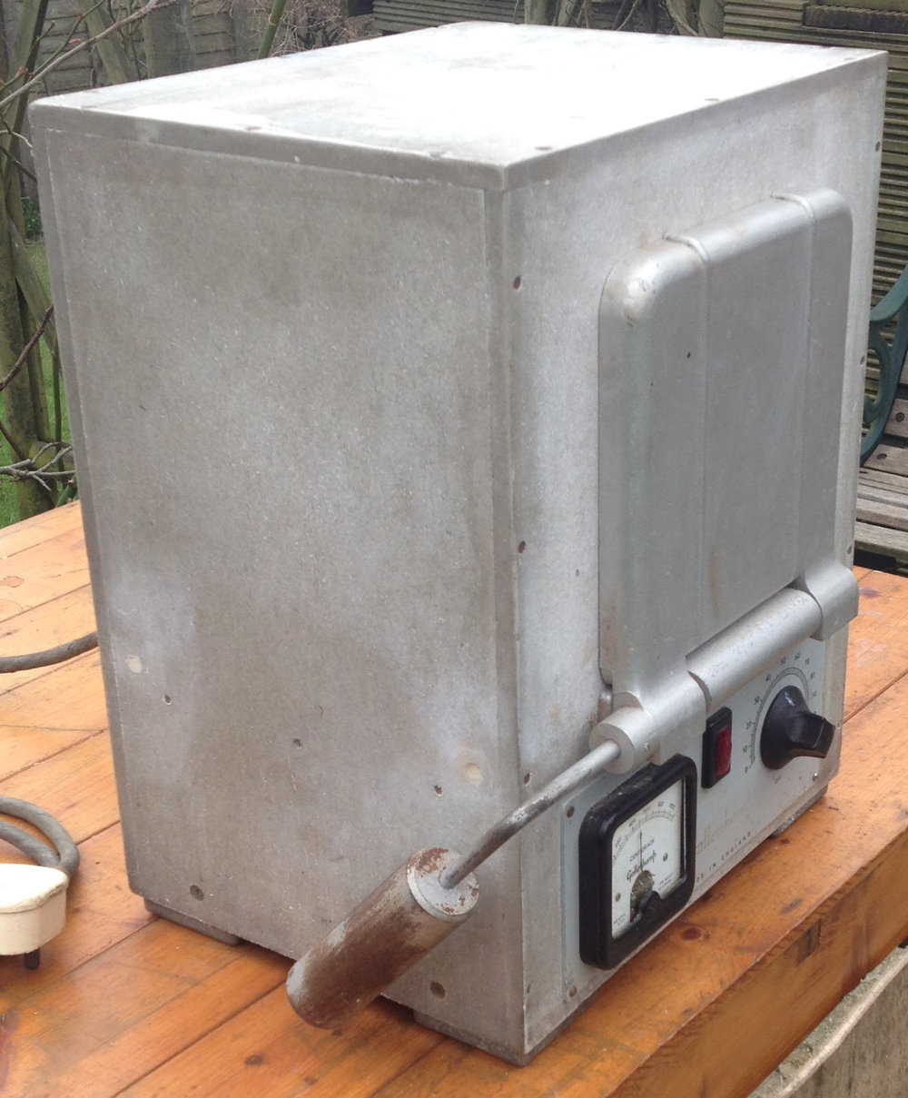
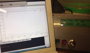
Recently I came across an old electric laboratory muffle furnace on eBay. Luckily I managed to get it very cheaply because it was described as faulty and it was near enough for me to collect it in person. It looked to be in good condition in the photos, and I figured that even if the heating element had burned out, it would be cheaper and easier to re-wind it than to build one from scratch.

heattreatoven1

The fault turned out to be very simple. It is supposed to have a fusible link inside the inner chamber that melts if you overheat it (a thermal fuse). This was probably quite easy to do because the original controller was a simple simmerstat3, and I suspect leaving it at 100% would cause it to reach melting point in about 45 minutes. The thermal fuse was missing. As a temporary measure I bypassed it and the oven fired straight up.

heattreatoven2

I learned nearly everything I know about heat-treatment of steel from Hardening, Tempering & Heat Treatment by Tubal Cain from the Model Engineer’s Workshop Practice series. It was only after I’d bought my oven that I happened to be flicking through the book and saw a picture of it: the author had the same model!

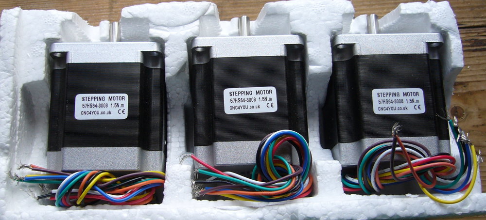
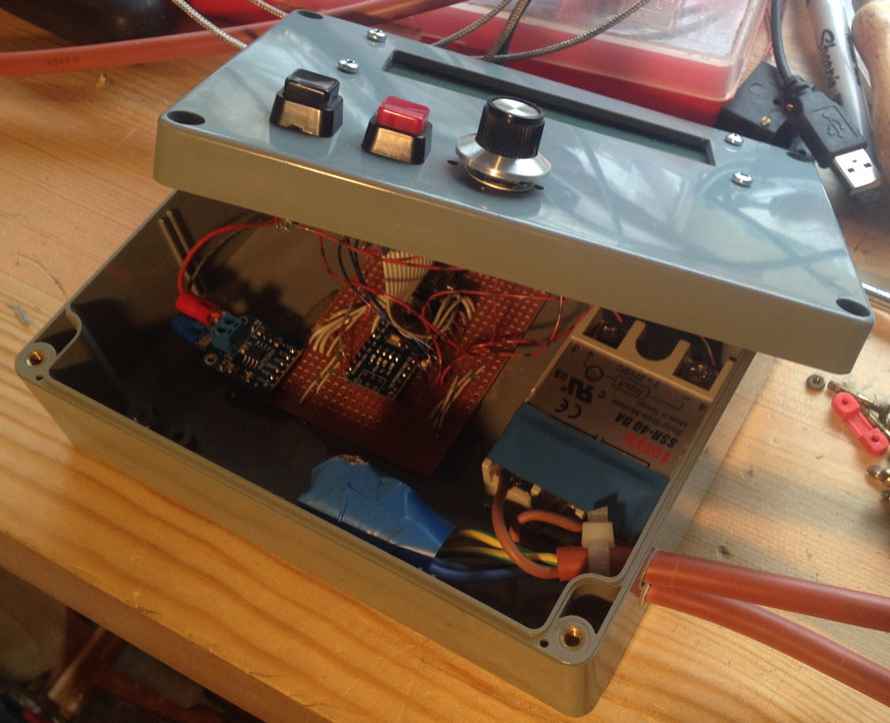
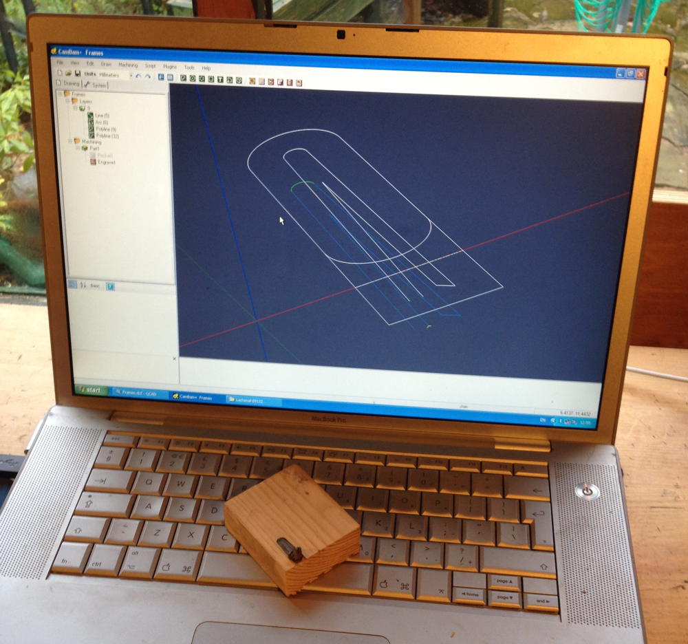
Tubal Cain had replaced the simmerstat in his heat treatment oven with an early computerised temperature controller. I wanted to do the same thing, and I could have simply bought a fairly cheap Chinese PID controller like the one I used on my glue pot (though high-temperature ones seem a bit harder to find and more expensive), but for various reasons I decided to build my own instead. I used a MAX31855 thermocouple interface from Adafruit, an Arduino Nano clone, a solid state relay, a 16×2 alphanumeric LCD (HD44780 compatible), a couple of push buttons and a rotary encoder stuffed into a plastic project box. Because I already had most of the parts other than the high-temperature K-type thermocouple (which I would have had to buy anyway) and the MAX31855, the project worked out pretty cheap.

heattreatoven3

I developed the firmware using the Arduino IDE and several off-the-shelf open source libraries. This is the first time I’ve used the Arduino system, though I’ve done quite a bit of embedded programming in the past. I must admit a decent C++ compiler and a large set of libraries made it pretty easy to quickly bolt something together, though the lack of a debugger is a bit of a pain, and some of the libraries are poorly documented and/or provided with example code that doesn’t work properly out of the box.

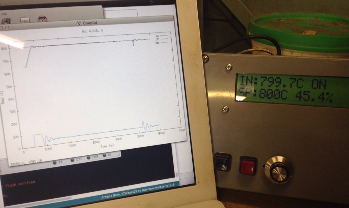
The most difficult part of the project turned out to be tuning the PID loop parameters. Get them wrong and the oven either never reaches the desired setpoint or it overshoots and oscillates around the setpoint. One advantage of developing my own Arduino-based controller was that it was easy to log the temperatures and power level at regular intervals to a laptop over USB, then plot a graph to figure out what was happening over time. To cut a long story short, after hours of test cycles and trying many different values, I eventually found a set of parameters that perform well enough for my purposes. It overshoots by a few degrees when it first gets up to temperature or after disturbing the system by opening the door, but I don’t believe that is enough to cause a problem. In this graph, the blip at 5200 seconds is the result of me opening the door for a few seconds:

heattreatoven4

For years I have been fascinated by how punches and dies were made prior to the invention of the rotary engraving machine. I’ve read what I’ve been able to find on the subject (not very much, to be honest) and studied some antique punches to try to work out how they were made. I decided to try making a punch from my maker’s mark to see if my ideas were practical.

I think positive punches and single-line name stamps usually used at least one counterpunch per letter to form the hollow spaces (the counters), and the outside waste was cut away with saws, files and probably a selection of gravers. There were also negative punches that were probably either entirely engraved or stamped with a set of reversed positive punches, but I’m not going to cover those today.

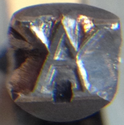
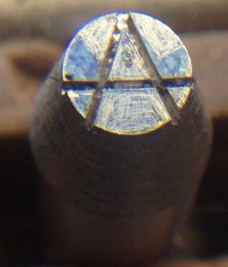
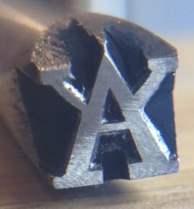
My maker’s mark is a fairly simple symbol (an upper case A with two arms added), though I wanted to challenge myself by making a serif version with multiple stroke widths.

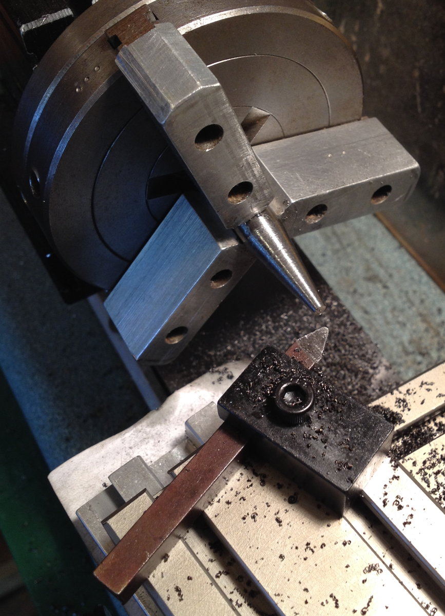
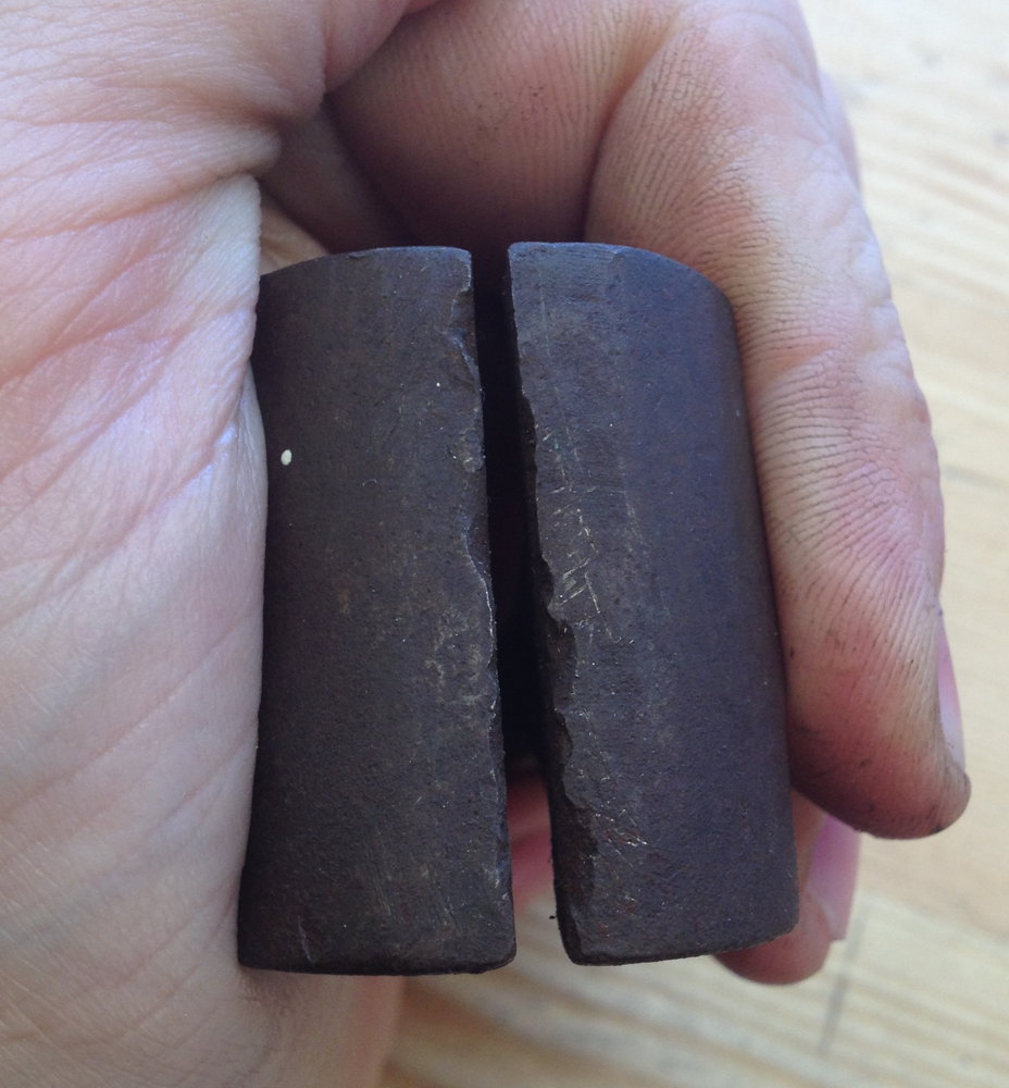
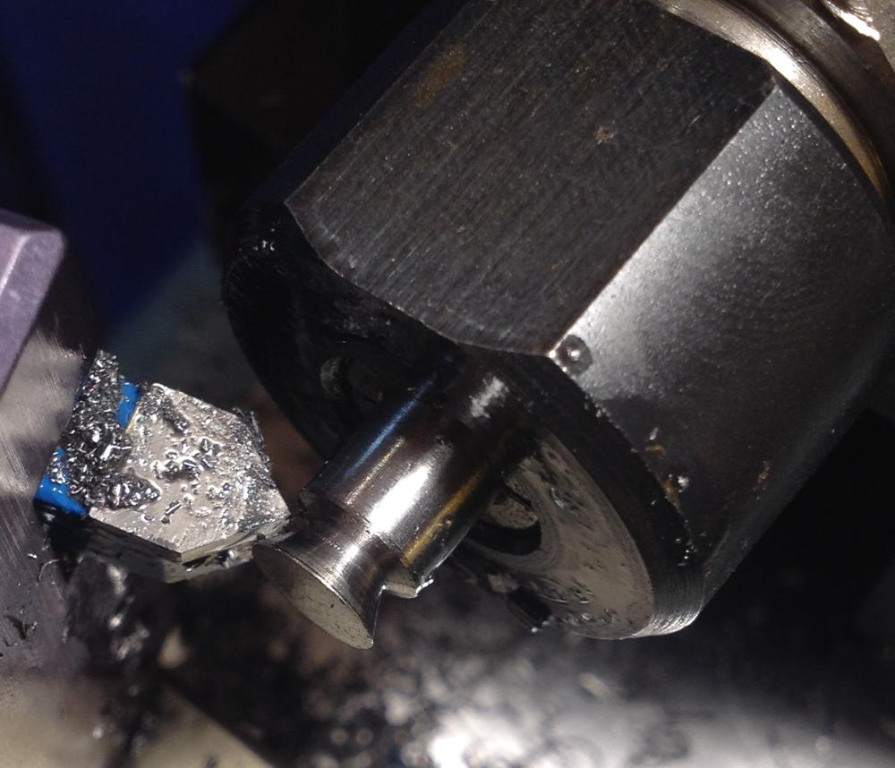
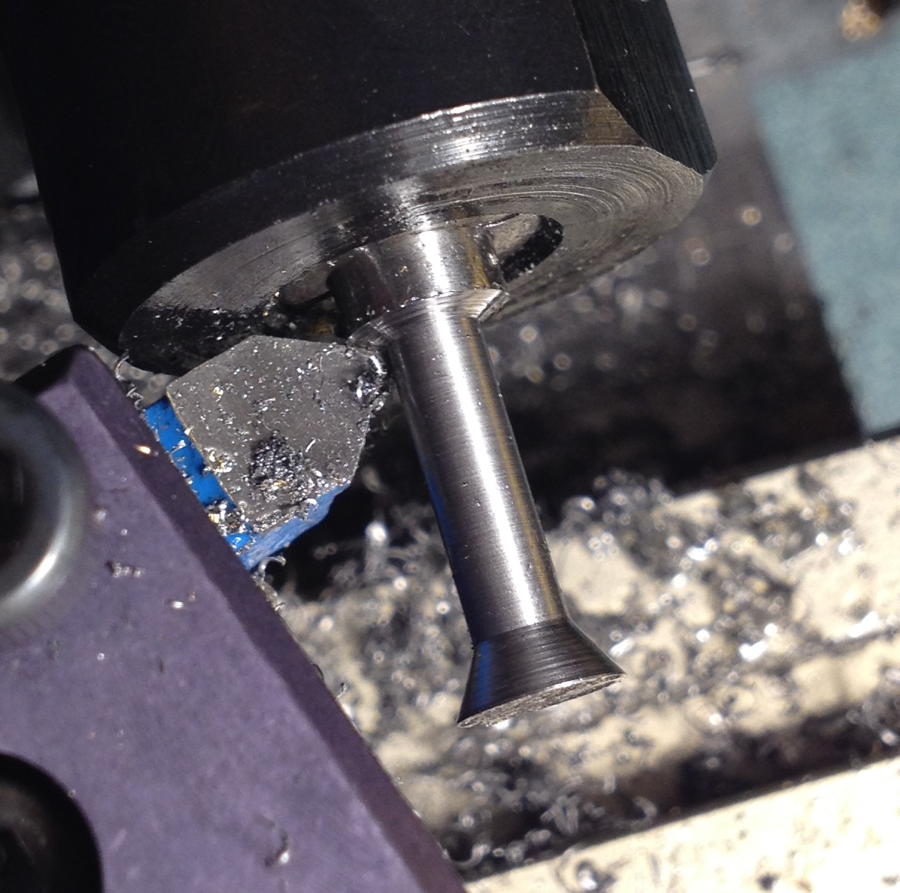
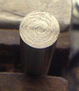
I made both the counterpunch and the punch from 3/8″ silver steel, which is a commonly-available high-carbon water-quenched tool steel with a little chromium in it that is supplied as accurately ground round bar. Since the counterpunch was to be smaller than the punch I first tapered the end. There are several ways to do this, but I decided to use the compound slide on my Taig lathe. I also used the lathe to face both ends to make them square, and used a file to round over the hammer ends a little so that when you strike it you don’t hit a corner.

punchmaking1

The facing process left the end that was to become the punch square and reasonably flat but very slightly rough. Because this might effect the performance of the finished punch I decided to lap it flat.

punchmaking2

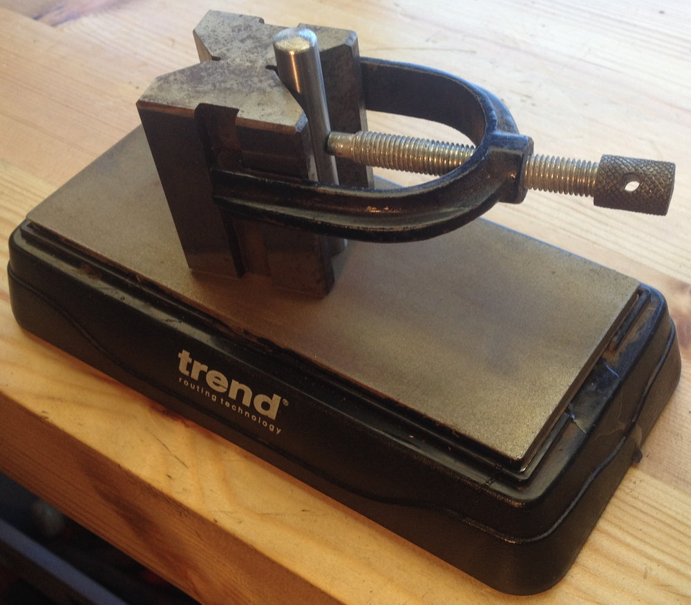
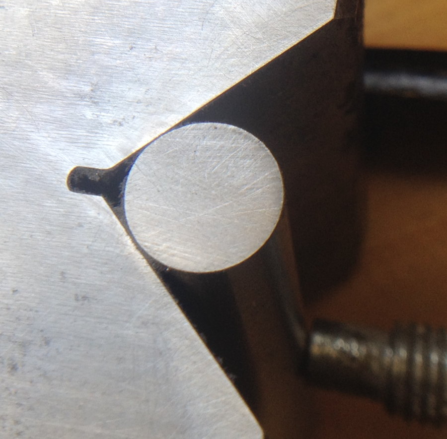
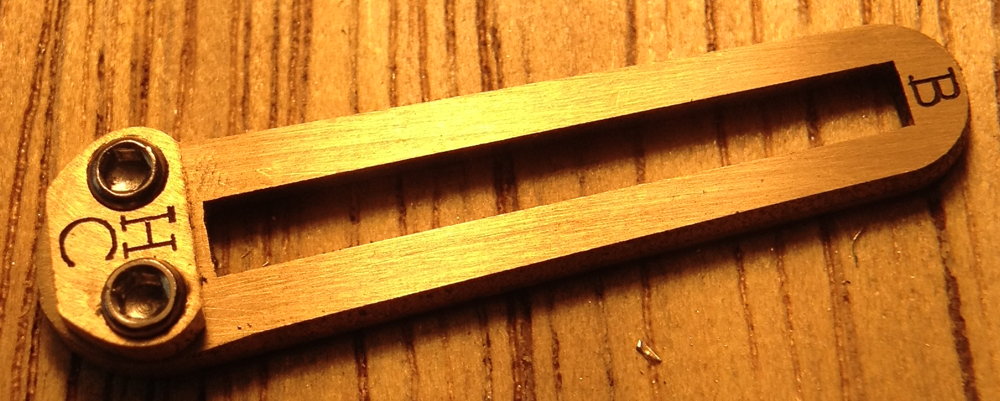
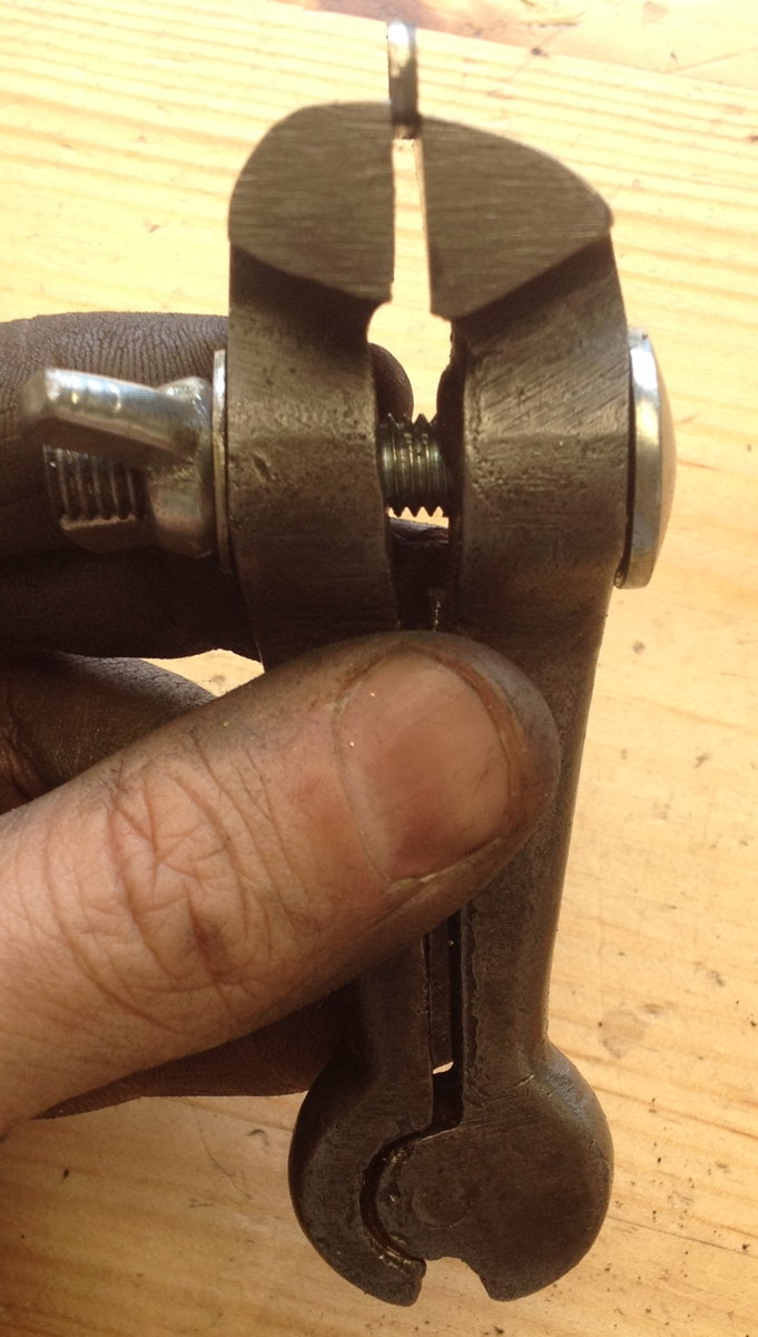
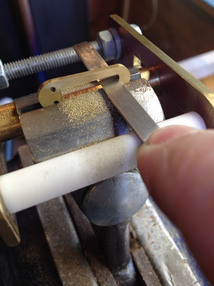
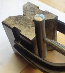
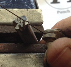
First I clamped the blank in a Vee block, using a piece of paper as a shim to make sure the punch protruded from the block by a tiny amount:

punchmaking3

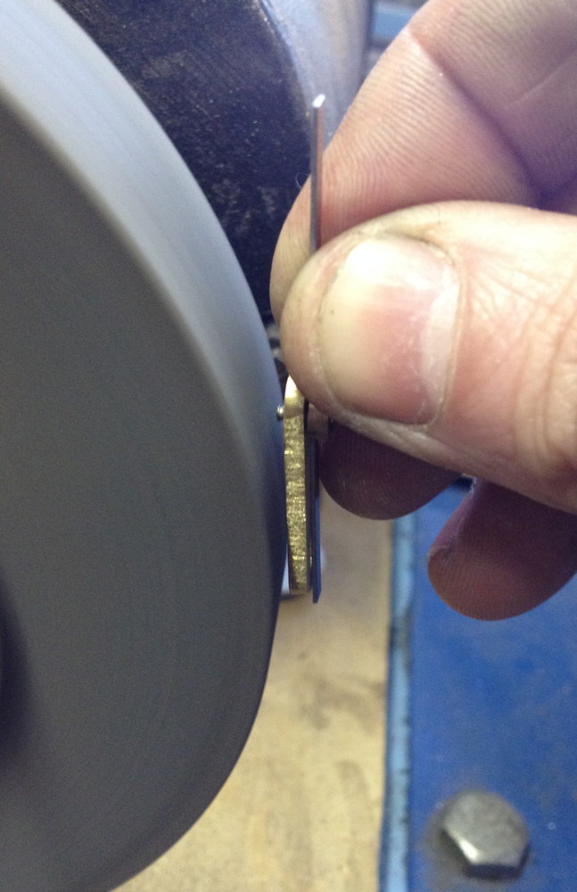
Then I lapped it on a cheap diamond plate in a figure-eight pattern:

punchmaking4

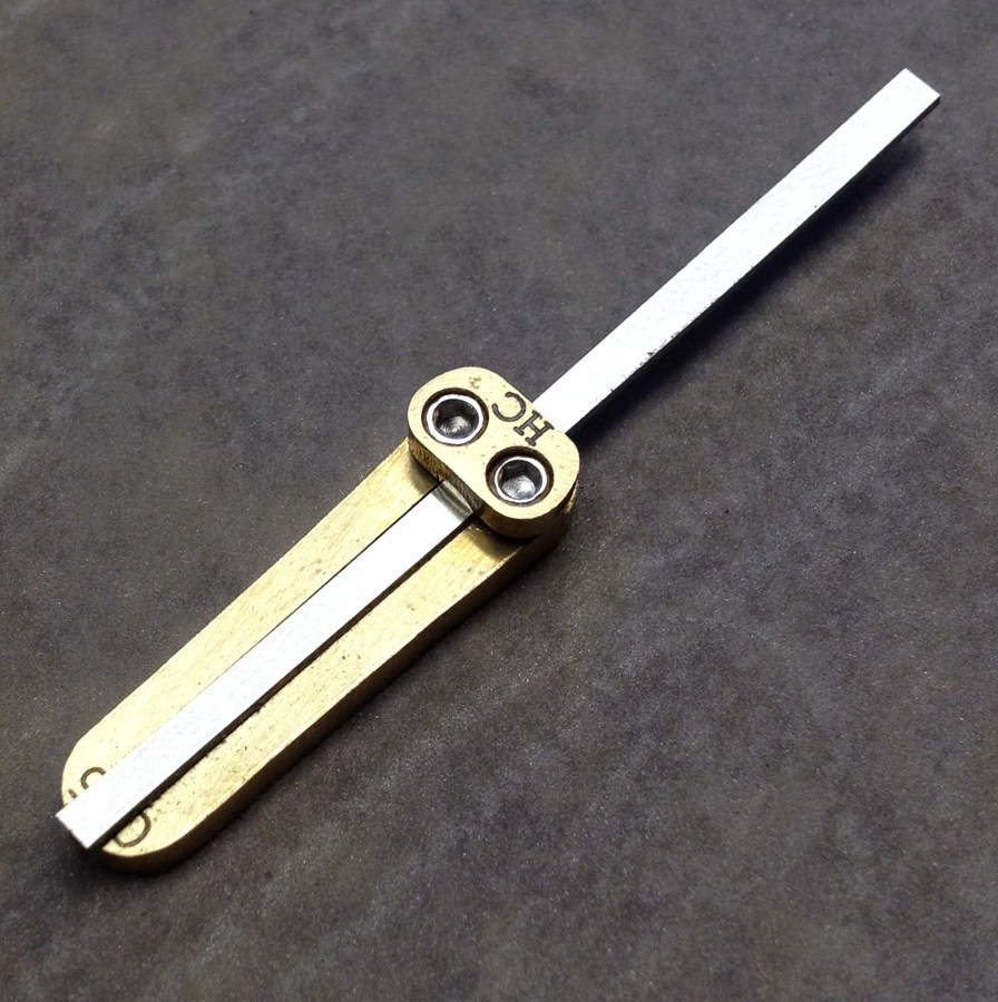
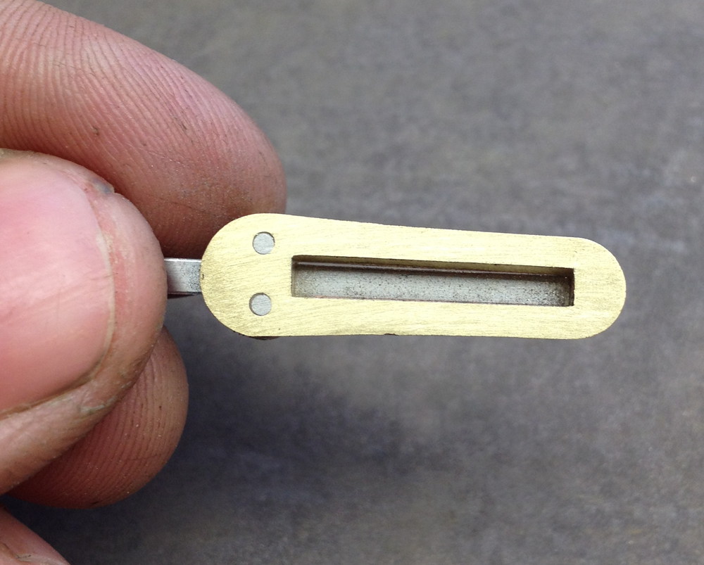
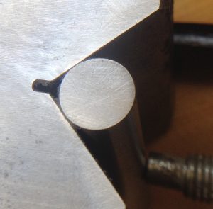
The lapped face of the punch blank:

punchmaking5

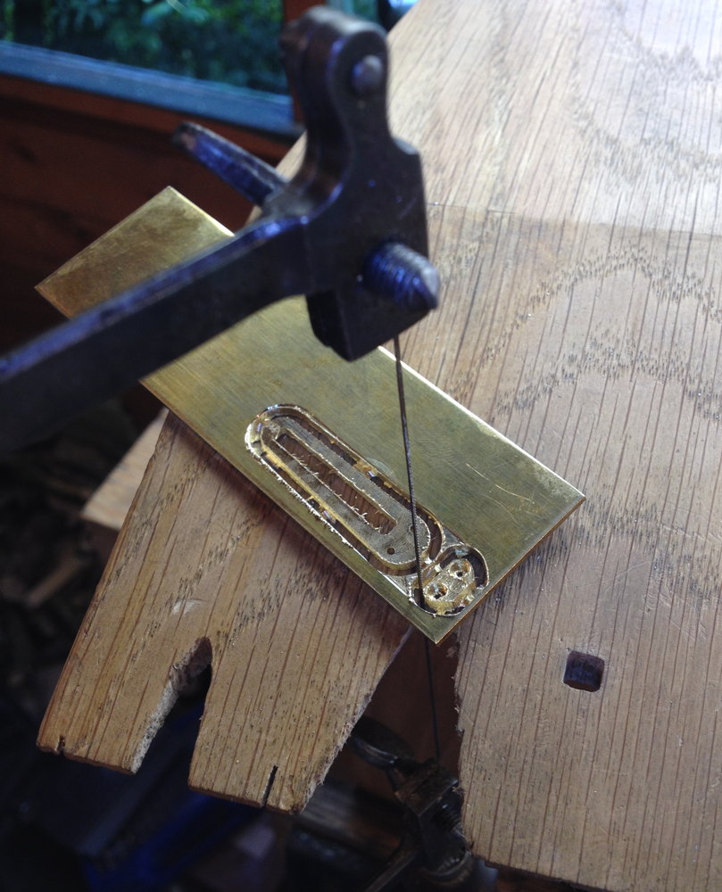
Next I started cutting the counterpunch using a jeweller’s saw to make the initial grooves:

punchmaking6

I removed the waste from the outside using a fine flat hand file:
punchmaking7

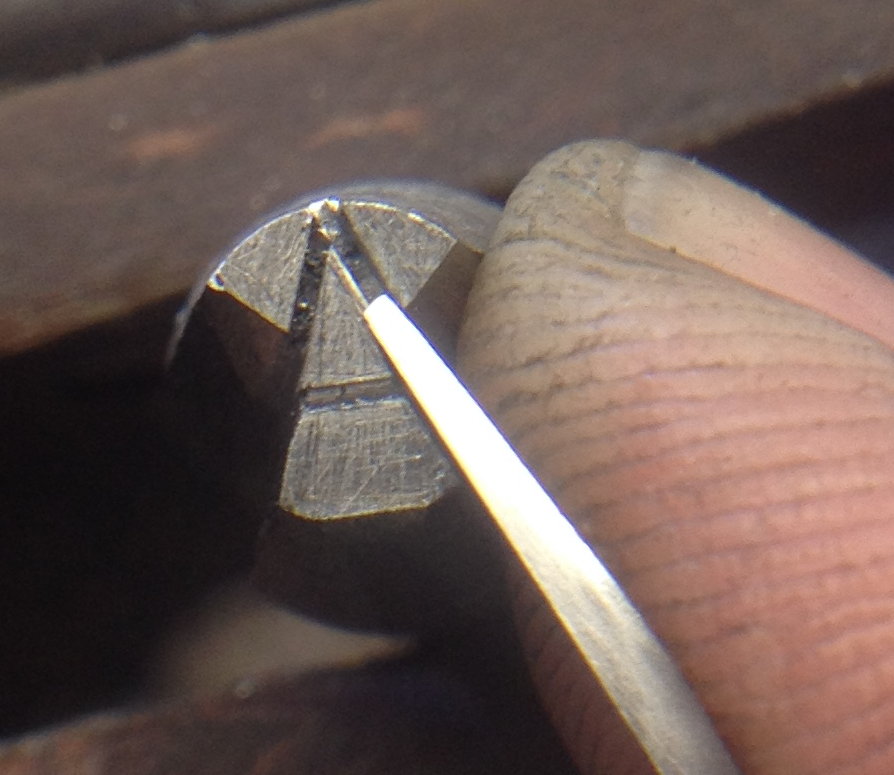
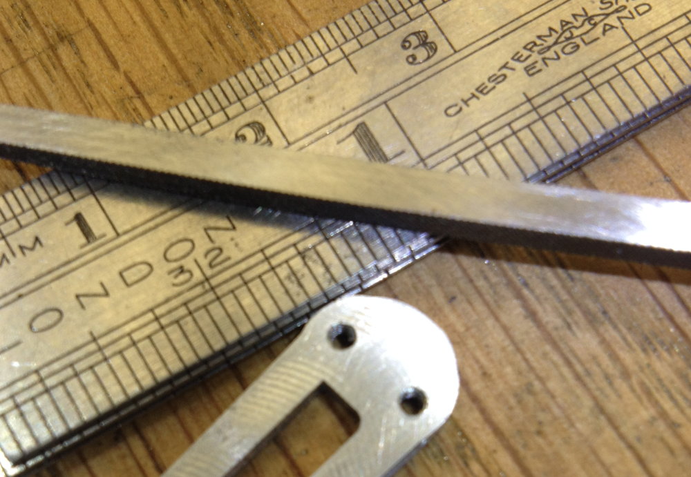
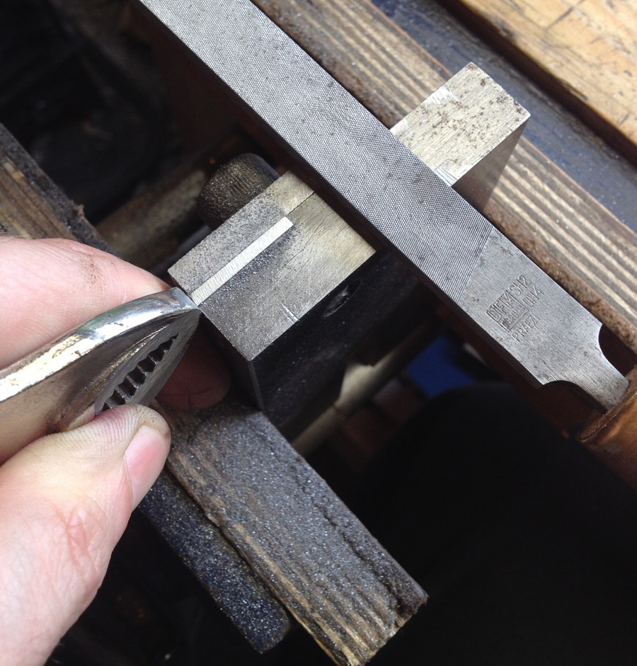
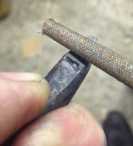
Then I used a graver to widen the grooves (you can see in this one it’s pretty small compared to my index finger):

punchmaking8

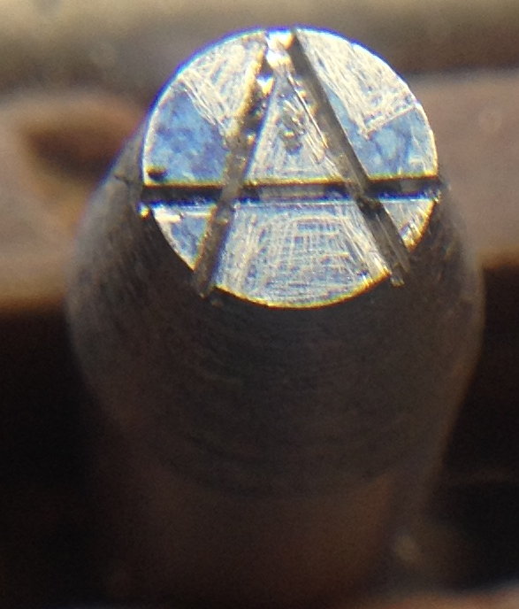
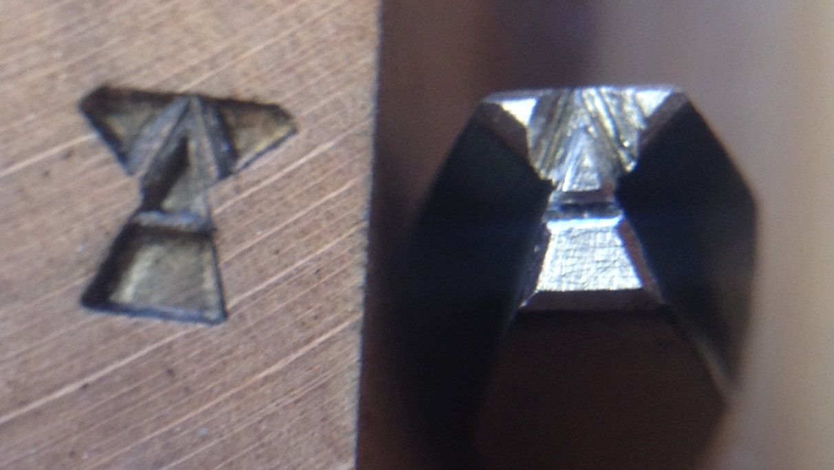
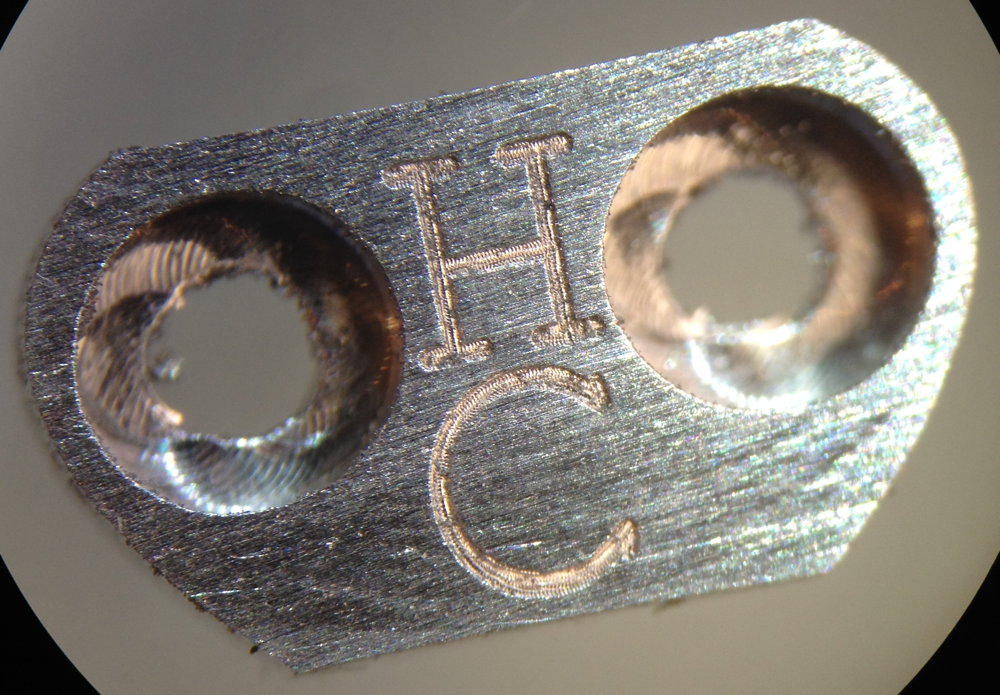
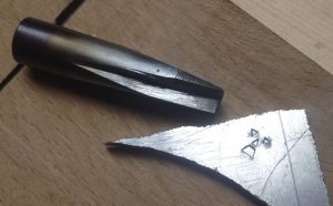
The nearly-finished counterpunch:

punchmaking9

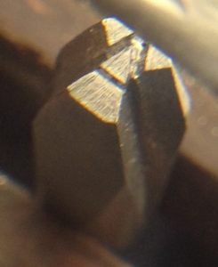
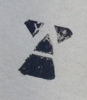
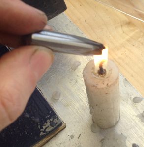
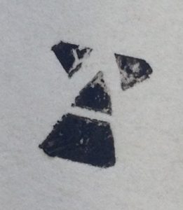
To check it was the right shape, I got it sooty in a candle flame and pressed it onto a piece of paper (this is called a smoke proof). Actually I realised at this stage that I had made a mistake, but I opted to push ahead and modify the proportions of the punch to compensate rather than starting again. I could get away with this because the design of my mark is rather fluid anyway, and doesn’t have to match the style of a particular font.

punchmaking10

punchmaking11

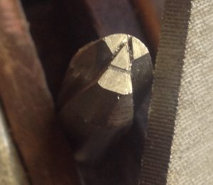
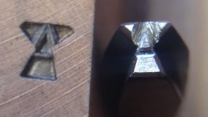
The final part of cutting the counterpunch was to bevel the corners and do a test punch into a piece of end-grain hardwood. I’ve found that a punch doesn’t work very well if you don’t bevel it at all, but it’s not entirely clear to me how steep the bevel angle should be (the old punches I’ve looked at aren’t all the same).

punchmaking12

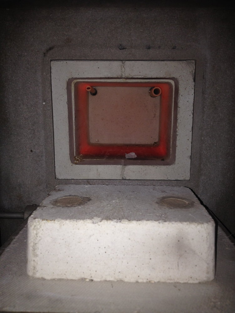
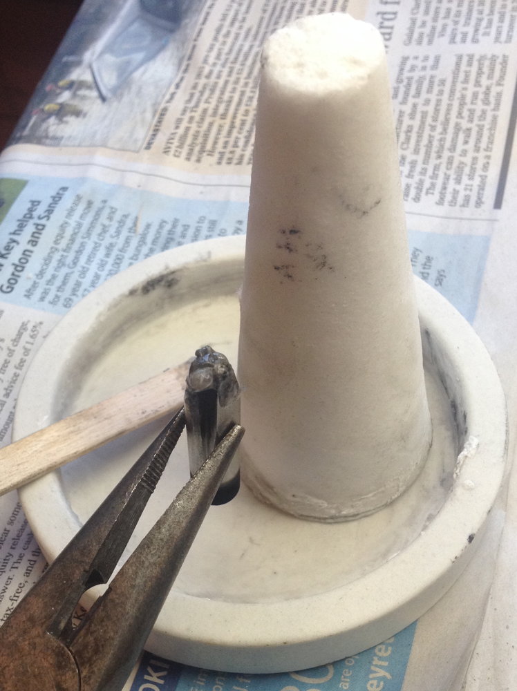
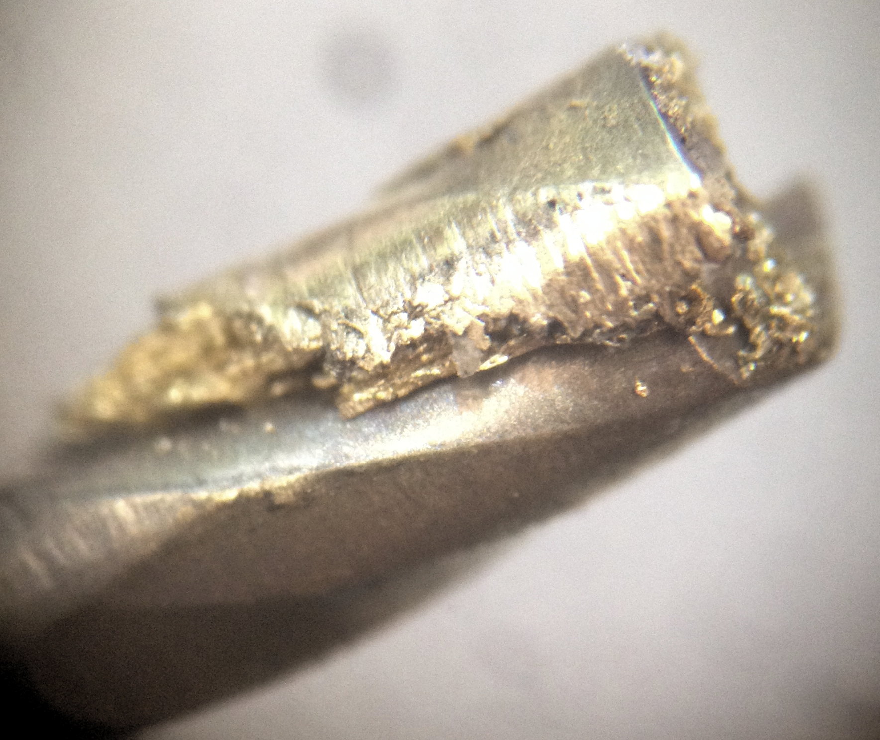
Next I had to harden the counterpunch before I could use it. In order to reduce scale buildup and decarburising while soaking in the heat treat oven, I coat the business end of the tool in jeweller’s borax flux. Applying it isn’t an exact science. I warm the punch to not-quite boiling point, then smear some thick borax paste onto it and wait for it to dry. Once in the oven, it will bubble up a bit at first but then it should melt and flow out across the surface (you can see the difference after heat-treating; the areas that were protected by the flux are still bright underneath).

punchmaking13

I put the counterpunch into the oven on top of a piece of bent stainless steel that prevents it directly touching the oven floor. After waiting something like 20 minutes for it to get up to temperature, I let it soak for another 20 to ensure that it was fully austenized all the way through. From what I’ve read, not soaking for long enough will significantly reduce the hardness you can achieve.
punchmaking14

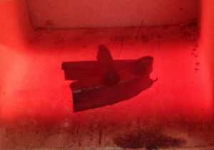
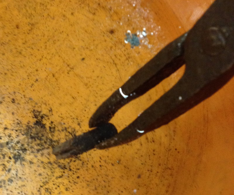
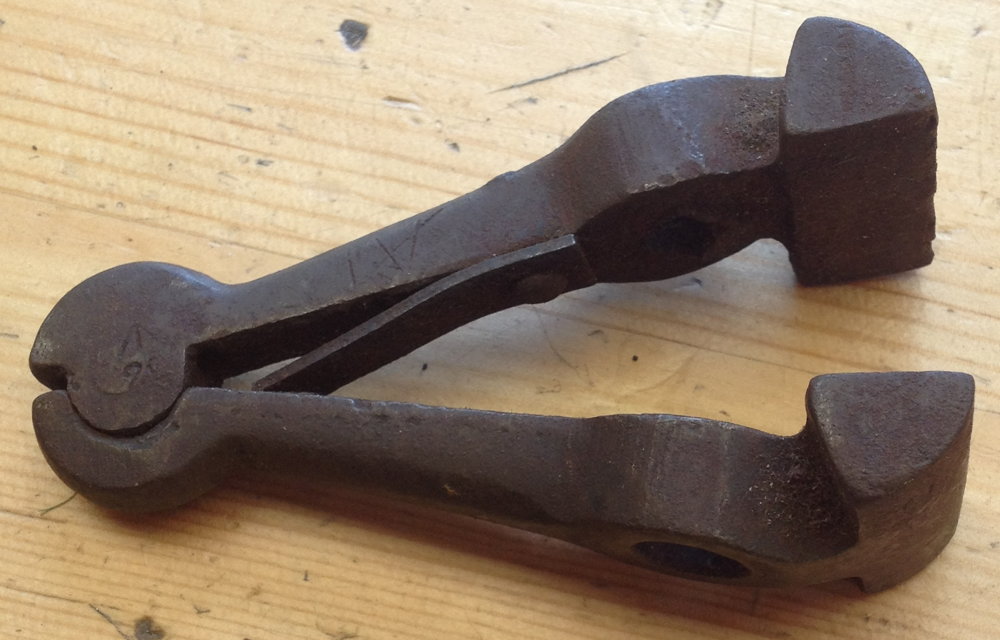
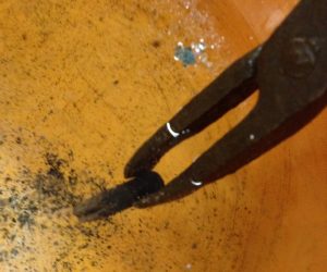
After soaking, I pulled it out with blacksmith’s tongs and immediately quenched it in a bucket of water. The shock actually causes most of the Borax flux to fall off, which is handy because it can be difficult to remove.

punchmaking15

As a quick check to make sure it hardened, I see if a file will cut it. Generally it will scratch a tiny bit because of the surface decarburisation effect but it will be hard enough underneath that the file just skates off. Some people recommend using a good sharp file for this test, but I find that it tends to blunt the file so I prefer using a rubbish file and just press quite hard (I have experienced a tool that didn’t harden properly and the difference was pretty obvious).
punchmaking16

After hardening, the steel is very hard but also very brittle and highly stressed. If you’re not careful you can shatter it just by rough handling (I’ve done that with a fancy spring clip that I had just spent half an hour forging). What we do to cure this is to temper it, which means re-heating it to a lower temperature and soaking it for a while. This reduces the hardness somewhat but also reduces the internal stress and greatly increases the toughness of the steel. If you temper it lightly you end up with quite a hard tool that might be at risk of chipping. Higher tempering yields a tougher but softer tool; if you go too far the edge may tend to roll over in use. The highest levels of tempering are used to make springs.

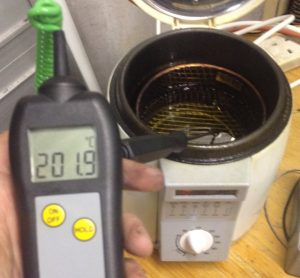
There are several ways to heat a tool for tempering. I could even use the heat treat oven itself, but it would take a few hours to cool down sufficiently and it’s not a good idea to leave the tool in its fully hard state for that long. I decided to use a small electric deep fat fryer with sunflower oil in it. The highest temperature the thermostat will go up to is about 200C (and the oil probably wouldn’t be happy going much higher than that), which is towards the low end for tempering silver steel.

punchmaking17

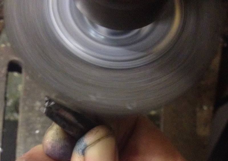
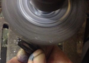
After tempering I used a rotary wire brush in the pillar drill to remove the scale and any remaining flux.

punchmaking18

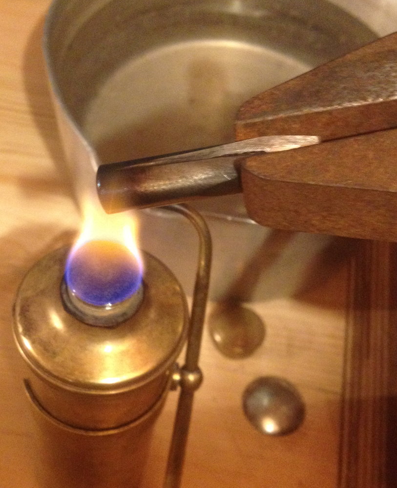
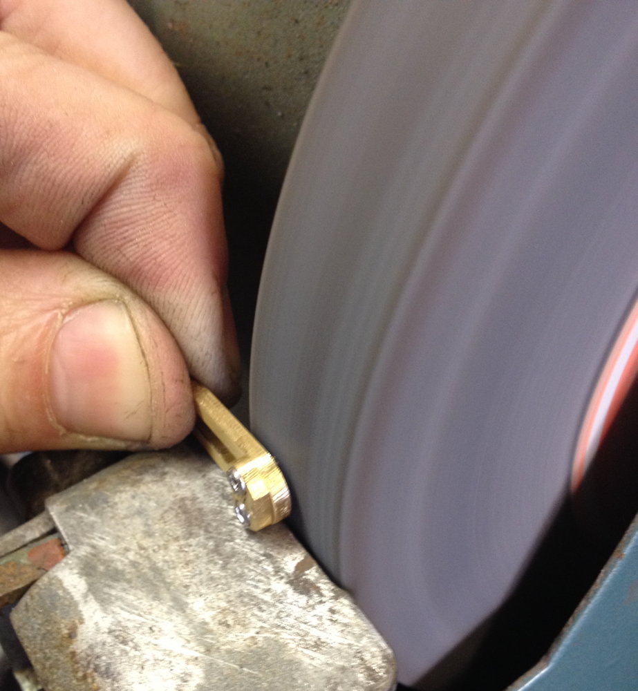
Finally I used a spirit burner to re-heat the blunt end up to a spring temper so that it can better resist the shock of hitting it with a hammer. It will probably mushroom eventually but it is easy to cure that by grinding. After it reached a blue colour I quenched it again to stop the heat travelling too far up the shank.

punchmaking19

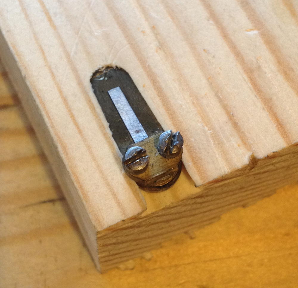
A quick test in a piece of scrap aluminium proved it had worked as planned:

punchmaking20

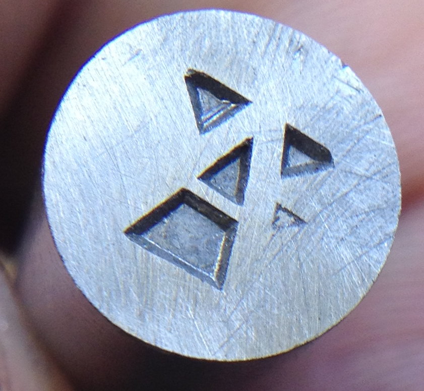
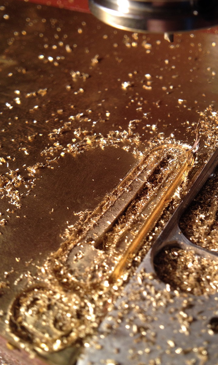
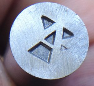
The first stage of cutting the real punch was to strike the counterpunch into it. I think this is possibly the most difficult part of the entire process. You have to line it up perfectly, then hit it multiple times very hard to drive it as deeply as possible into the steel. Although the silver steel is supplied annealed, it is still a pretty tough material and it takes a lot of force to counterpunch it. The counterpunch bounces out of the indentations after every strike and you have to be very careful to line it back up perfectly before the next strike – I had a bit of an accident and made an extra small dent but luckily it was in a waste area. The counterpunching causes the surface to raise up a bit around each indentation, which I opted to get rid of by lapping it flat again. Here is the result after counterpunching and lapping:

punchmaking20b

I roughly removed the majority of the waste from the outside with a jeweller’s saw and files again:

punchmaking21

Mostly done, though not yet adjusted the width of the strokes:

punchmaking22

After a bit more fine fettling, and adding the bevels:

punchmaking23

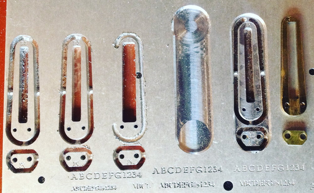
I didn’t bother photographing the hardening process as it was exactly the same as for the counterpunch. The final set of photos shows the result of testing it in several different materials. First end-grain beech:

punchmaking24

Aluminium, both a light strike and a heavy one:

punchmaking25

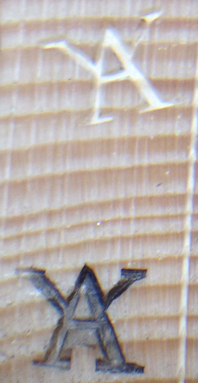
A light strike into side-grain pine tended to crush the soft fibres:

punchmaking26

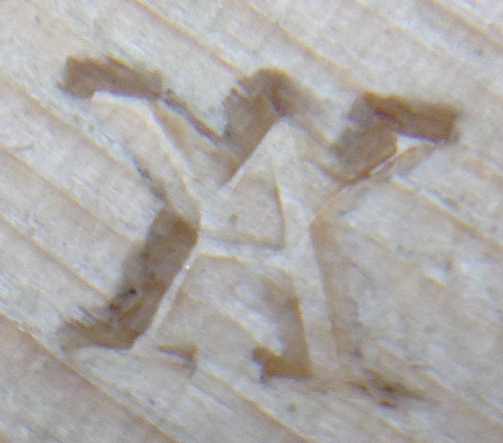
End-grain pine worked fairly well though. The bottom one was an experiment in soot blackening the punch first:

punchmaking27

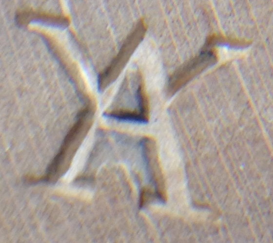
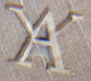
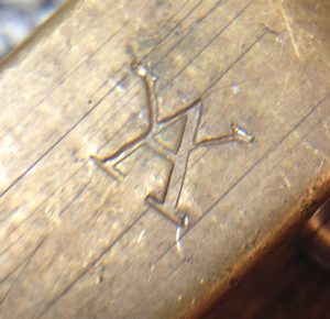
Brass. I had to hit it pretty hard to get a decent impression but it came out quite nicely:

punchmaking28

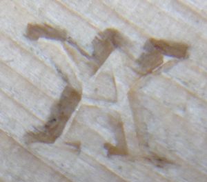
Thick leather. This looks sharper in reality than the photo appears to show:

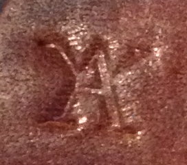
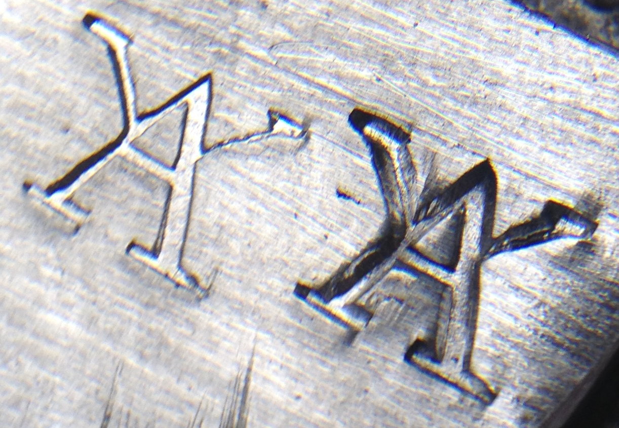
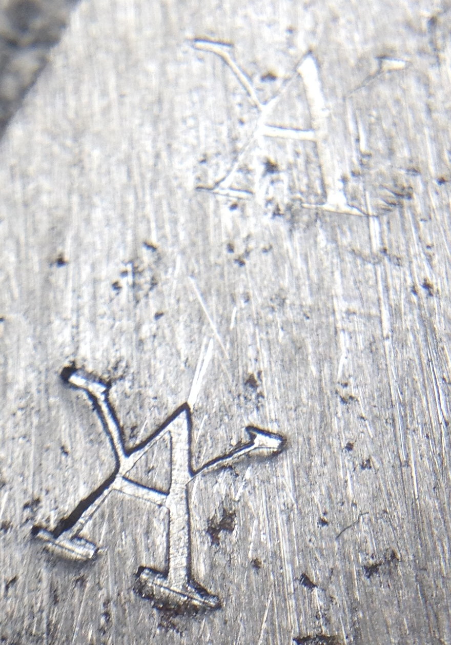
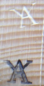
Mild steel. The top mark was a moderately hard strike onto the wooden bench and it’s barely visible. The bottom mark was a very hard strike backed by a steel anvil. I’m not sure I’d want to risk striking the punch that hard very often as I’m concerned the tiny serifs might be at risk of breaking off, though it didn’t suffer any visible damage as a result.

punchmaking30

Reed Prototypes Part 1: Frame and Clamp

Recently I made my first prototype concertina reeds. There’s a lot to write about so I’m going to divide it into two articles, this one will cover the frames and clamps, and the next one will cover the tongues.

My plan was to make a drop-in replacement for one of the low ‘B’ reeds in my vintage Lachenal English. I think this instrument was probably one of Lachenal’s higher-end ‘broad scale’ models, because I also have another steel-reeded Lachenal that in many cases has narrower reed tongues in the same pitch. I’m not totally sure why the narrow scale models existed or were originally cheaper than the broad scale equivalent (the extra metal and labour is fairly trivial). They were probably quieter at the top end of the dynamic range, which might make them better for a student instrument.

I understand Wheatstone’s earliest reeds were made totally by hand, piercing them with a jewellers’ saw and cleaning them up with files. This must have been very labour-intensive, highly-skilled work, and prone to inconsistency. At some point fairly early on, perhaps when Louis Lachenal was hired to mechanise production(?), they changed to using fly-presses and dies to punch out the reed frames. This was much faster, worked well, and the presses could be operated by relatively unskilled workers, but the disadvantage is that precision dies are very expensive to make. To save on tooling costs, instead of making a different set of dies for every pitch of reed, they made do with a handful of sizes and made up for the gaps between them through careful tongue profiling. Until relatively recently, the need to invest in a set of press tooling was a significant barrier to entry for new reedmakers.

Enter CNC machining. I understand other makers have successfully used laser cutting or possibly wire EDM, but I have my own small CNC milling machine so that is the process I am going to use. It is fairly slow (certainly compared to a a press tool), but it works pretty well and I hope to get to the stage where I can load in enough brass for half an instrument worth of reed frames, and set it going with minimal supervision while I work on another task. As well as cutting out the shapes of the frames and clamps, it can also cut the vent slots (albeit with filleted corners), drill the clamp holes, engrave the note labels and a logo, counterbore the clamp screw holes, and even chamfer the top edges of the frame so they fit nicely into the dovetailed slots of the reed pan. Initially I’m planning to copy all the dimensions of my prototype reeds from the Lachenal instrument, but in future when I understand the design parameters better I will be able to make frames that are the optimal size for each pitch.

My first attempts at milling frames were using scrap aluminium. It took me quite a few failed attempts before I got one that seemed pretty good (the antique Lachenal frame I was copying is on the right):

aluminium_reed_attempts

Next I moved onto brass prototypes, immediately running into problems with it cutting very badly and breaking 1/16″ end mills:

failed_brass_reed_shoe

A microscope view of an end mill with clogged flutes, from a run that I aborted before it snapped:

clogged_end_mill

I think the reason for my problem was that the chips weren’t clearing from the slots properly so on subsequent passes they were getting re-cut and generating a lot of heat. I experimented with a lot of parameters, but basically what worked was making the depth of cut shallower, increasing the spindle speed to 10K RPM (the maximum my machine’s spindle can handle), significantly increasing the feed rate (to make bigger chips), and adding a compressed air blast to blow the chips away. I also changed from two flute HSS bits to three flute cobalt bits, though I’m not certain that helped with the chip clearance (it did allow me to increase the feed rate a bit more). It also proved necessary to make some proper mechanical clamps to hold the plate to the spoil board, because double-sided tape wasn’t holding it securely enough:

sheet_metal_mill_clamps

Here is a (21 minute long) video of the process of milling a single reed shoe prototype. Don’t bother watching the whole thing unless you’re really fascinated! This isn’t quite the final program: I subsequently altered the bevelling operation slightly so that the frame wedges more securely into the reed pan.

The CNC program includes small tabs that prevent the parts coming loose during machining. Afterwards these need to be manually cut. I found that it was possible to break them out with a small chisel but it left rough stubs that I then had to clean up with a file, so I changed to cutting them with a jeweller’s saw:

cutting_reed_frame_tabs

Because I cut the vents using a 1/16″ end mill, this leaves 1/32″ radius fillets in the corners, which should ideally be dead sharp. I’ve been manually cleaning these up using a fine square needle file with one edge ground smooth. I put the reed frame over the small square hole in my bench peg (see previous photo), hold the safe face of the file flat against the end of the vent, and carefully file sideways into the corner until it’s as sharp as possible without leaving a nick:

reed_vent_squaring

The clamp screws I’m using are a bit smaller than the originals; they are M1.6, stainless steel, with 2.5mm diameter allen heads:

clamp_screw_comparison

In my testing they are strong enough for the purpose and take up less space than the originals, and the finer pitch and allen heads make them easier to tighten and loosen without damaging them.

When tapping the clamp screw holes in the frame, it’s very important to keep the tap perpendicular to the hole. After researching tapping machines and complicated guides, I came up with this simple method that works surprisingly well (though I still managed to break a tap the first time I tried to tap one of the brass shoes!):

I added counterbores to the holes in the clamps because it was easy to do and significantly reduces the height of the reed without weakening the clamping ability. It also improves the accuracy of the location slightly. Because I was already using an engraving operation for the note labels, I added a simple brand to the clamp (HC=Holden Concertinas):

reed_clamp

Because the screws start out a couple of mm too long, I put them in the frame and grind them almost flush with the bottom of the frame, then finish them off with emery paper on a sheet of glass:

grinding_clamp_screws

One of the defining characteristics of traditional concertina reed shoes is that the underside of the vent is relieved (i.e. the bottom of the slot is slightly wider than the top). My current understanding is that this allows the reed to work properly even at very low bellows pressures, i.e. it enables you to play quietly if you want to. It also has an effect on the tone. I’m not doing this on the milling machine because there are good reasons to cut them out from the top and it would be a bit tricky to turn them over and accurately register them for an extra operation. Instead, I made a special jig that allows me to file the vent to a consistent angle using a flat needle file with two safe narrow edges.

The clamp part of the filing jig started out as an old war-surplus hand vice with damaged jaws:

vent_filing_jig_1

vent_filing_jig_2

I trued up the jaws and modified the profile of the front jaw so that there is room for the file to tilt down below the level of the back jaw:

vent_filing_jig_3

Next I added an adjustable brass frame and a PTFE roller to guide the file, as shown in the following video. I align the top edge of the vent with the top of the back jaw, paint the inside of the vent with a black marker pen, and file until I’ve almost but not quite removed all the ink.

Here we have my first brass reed frame in my Lachenal reed pan. You can see how much lower-profile the new screw heads are: I think this might help with air flow inside the reed chambers. It took several prototypes before I was totally happy with the tightness of the fit in the dovetailed slot. There is a small area around the clamp that isn’t fully bevelled, giving a nice friction fit without compressing the sides of the frame adjacent to the vent.

reed_frame_finished

finished_brass_reed_frame

Reed Pan Router Bit

I’ve spent hours searching for a commercially-made router bit that has the right dimensions to cut the dovetail slots in a traditional reed pan. It needs to be an unusually small diameter, but if you want to be able to cut the top slots after installing the chamber side walls as it was done originally (some of them undercut the walls), it needs to have a disproportionately long ‘neck’ between the cutter and the shank. On the plus side, the slot is quite shallow so the neck doesn’t need to be ridiculously skinny. In the end I decided to make my own.

I started with a piece of 1/4″ silver steel. After putting it in a collet and facing the end, I used the side of a threading tool to turn the tapered section, being careful to produce a sharp corner without significantly reducing the diameter of the base of the cone. I made it just long enough to be able to cut a 2mm deep slot, to avoid weakening the neck section unnecessarily. I set the tool holder over to produce the desired 60° taper:

dovetailbit2

Next I extended some more stock from the collet and turned the ‘neck’. On my first attempt, swarf obscured my view of the work and I accidentally retracted the carriage too far to the right and put a groove in the cone area. There was no option but to start again! The second time, I used the tailstock as a right-hand carriage stop to protect the cone.

dovetailbit3

The trickiest part of making your own router bit is producing the flutes without a special tool cutter/grinder machine. I cut three helical flutes by hand with a very small triangular saw file, then hardened and tempered it and sharpened the edges with diamond needle files:

dovetailbit4

Unfortunately it didn’t work well at all. It splintered the surface badly, then overheated:

dovetailbit5

Back to the drawing board. I studied a lot of photos of commercial dovetail router bits on Google Images and came up with a very different two-flute shape. Here’s a quick clip of me filing the relief angles on the second router bit with my saw file (click to stop it after you’ve seen it once, because the Instagram player auto-repeats):

https://www.instagram.com/p/BNC0Pi6APbx/?taken-by=alexholdenmaker

And this is the finished bit, after heat treatment and sharpening. The thing it’s inserted into is one of my milling machine’s quick change tool holders:

dovetailbit6

This photo shows the reason why it needs a long neck (I made it a bit longer than would have been necessary for this Treble English, in case I want to make an instrument with deeper bass reed chambers at some point):

dovetailbit7

The second router bit works pretty well. Here’s a clip of it cutting a reed slot in a piece of scrap pine:

Programming the CNC mill to machine the slots is surprisingly complicated. The CAM software I’m using doesn’t understand how to cut a pocket with a tool that can’t plunge straight the workpiece and needs to enter and leave the edge of the material. I found a way to trick it into doing what I need, but the entire process filled nearly two pages of my logbook, and I need to do it all again for every size of frame I need to cut!

dovetailbit8

Another problem I ran into is that the outer dimensions of the antique Lachenal reeds I’ve been copying are a bit variable. Not by much, but a tenth of a mm change in width makes the difference between a snug fit and a loose one. This one fits very well – I can throw the block of wood in the air and catch it and the reed is still nicely seated – but the reed taken from the slot next to it (nominally the same frame size) is loose enough that it would fall out. I think when the instrument was built, somebody must have spent a while individually fitting each reed to its slot. Luckily my CNC mill (which I’m using for both the frames and pans) is repeatable to tight enough tolerances that I shouldn’t have this problem.

dovetailbit9

No. 1: Brun Part 6: Reeds

The sixth instalment in the story of how I built my first concertina is about the reeds. I’m not going to cover every step of the process because it was very similar to my previous posts on the subject, apart from a few minor improvements and the fact that I had to make sixty of them in twenty four different pitches.

Something unusual I did (it might even be the first time it’s been done by a concertina maker) is I made a different size of frame for every pitch instead of making do with a limited number of frame sizes, each one being used for two, three or even four pitches. I started by measuring the vent dimensions of the reeds in a Lachenal English I own and plotting them on a graph. They were pretty lumpy but they followed a general trend. I then fitted curves to the graph and used them to derive a formula for the reed scaling. I plugged those formulas into a spreadsheet, which calculated the vent dimensions for all the pitches I needed. The outer frames were all the same angle and tip radius, with a constant distance between the tip of the frame and the tip of the vent. A slight drawback with the way I did it is that the longer reeds ended up with thinner edges than the shorter ones; when I design the next set I may try to come up with a way to reduce that effect.

I have since learned that the reeds I based my scale on were probably what is known as “short scale”. A fellow maker sent me a set of measurements of reeds from a higher quality vintage instrument, which appears to have both longer low reeds and shorter high ones, i.e. the range of pitches is stretched out over a wider range of lengths. I understand short scale reeds were typically used when the maker needed to fit a lot of reeds into a given space, which actually makes a lot of sense for this particular instrument because the reed pans are very tightly packed. I don’t think I could have fit long scale reeds in it if I had tried. My next concertina will have the same number of buttons in a larger instrument, so I plan to use longer scale reeds in it. I have been told that longer scale reeds have better pitch stability and responsiveness, particularly on the low end.

As before, I cut the frames and clamps from 2mm brass sheet on my CNC milling machine. This time I left them at the full 2mm thickness.

When I did the prototype reeds, each frame took a very long time to mill. Before I made the first full set I spent a while experimenting with feed rates and depth of cut (wasted some material and broke a couple of end mills in the process), and came up with a reliable rate that is significantly faster than what I was using before. I also dropped what was by far the slowest part of the process: bevelling the edges of the frames with lots of tiny steps. They now come out of the milling stage with straight sides.

The full set of sixty frames and clamps, before cutting them free of the stock.

After cutting them free, I tapped all 120 clamp holes and screwed them together. The clamp is a different size for each pitch too, so it’s important not to mix them up!

I filed off the flashing and the remains of the tabs with a hand file. In hindsight it would have been quicker to use my die filer to clean up the frames, though the clamps are probably too small to do that way.

A little improvised fixture to hold each reed frame while I square up the vent corners with a needle file. It’s crucial to get the tip corners as perfect as possible otherwise you can’t get the tongue to fit really closely without clipping the frame.

The vent relief angles on my Lachenal reeds were very inconsistent and often rounded; I suspect they were quickly filed by eye without a guide. I set my guide to an angle that was roughly the average of the angles on the Lachenal reeds and used it for all of my reeds.

I used my die filing machine with the table tilted over to 7.5° to bevel the frame edges, filing up to a line engraved by the CNC mill. I deliberately left them a bit on the tight side, then later on after I’d made the reed pans, I hand fitted each frame to its slot with a hand file.

https://www.instagram.com/p/BTTeGiqjHiH/

I shortened the clamp screws by first clamping the reed tongue blank in the frame, then grinding the screws almost all the way on a slow grinding wheel, followed by lapping them flat on a piece of fine emery paper glued to a sheet of glass.

All the tongues roughly sheared to size.

Draw filing the edges of the tongues to clean them up, then fitting them precisely to their frame with the aid of my microscope. This is probably the most difficult and painstaking part of the process to get right.

All the tongues initially fitted to their frames; many hours of work have gone into them at this point.

My file was feeling pretty dull so I had a look at it under the microscope. All the teeth had their edges fractured off. No wonder it wasn’t cutting so well any more!

I probably should have bought a new file at this point but I kept going and did much of the profiling with it (I also used a three square file for some of the work). I can’t remember if I’ve written about the fixture in this picture before. It has an adjustable-height step that you place the tongue against. The clamp is a pair of locking pliers that have been modified to have a sharper nose.

The full set of reeds, profiled and rough-tuned. They start out very high initially and go lower as you profile them. I stopped filing when they reached somewhere between +5 and +20 cents sharp on the tuning bench, knowing that they were likely to go a bit flatter once in the instrument. The way they are arranged in this photo shows the unisonoric reed pairs for the left hand on top and the right hand on the bottom, with a few notes of overlap in the middle. If it was an English or Anglo concertina the distribution would look very different.

It’s been said by other makers that, of the many time-consuming stages involved in making an English-style concertina from scratch, the reeds are the greatest. I think I can definitely agree with that statement. I probably spent at least a couple of hours on every reed, maybe more when I include time later spent troubleshooting and fine-tuning.

A Müller Conversion

My latest project was to make a pair of new replacement action boxes for a Wheatstone model 21 English concertina, to give it a keyboard and handrails/straps to the specification developed by Henrik Müller. The conversion was done in a manner that allows the instrument to be easily returned to its original form if desired. As I write this post, Henrik is working on an article for the Concertina Journal that should answer the question of why one might wish to mess with improve upon Charles Wheatstone’s nearly two-hundred-year-old design.

No. 4: A 44 Button Crane Duet

My latest instrument is another Crane duet, this time a traditional-looking 44 button (+ air) with 6 1/4″ hexagonal ends.

Here is its full specification:

  • 44+1 button Crane layout with Butterworth curve and slightly narrowed column spacing.
  • Six sides.
  • Weight: 1170g.
  • Seven fold plain black goatskin bellows.
  • Black walnut burr veneer with black Rocklite Ebano border inlay.
  • Ebonized beech handrails with integral strap fixings.
  • French polished finish.
  • 6082-T6 aluminium reed frames with steel reed tongues.
  • Standard scale reeds on the left hand, long scale on the right hand.
  • Sycamore radial tapered reed pans.
  • Sycamore action boards.
  • Brass sheet riveted action levers.
  • 3/16″ nickel silver capped buttons with acetal cores.
  • 2mm button travel (giving 4mm pad lift at 2:1 action lever ratio).
  • Black wool bushings.
  • Tuning: 1/5 comma meantone with root note A=440Hz.
  • Includes some modifications to standard Crane layout, such as the addition of left hand A2, Bb2, and B2 notes, and right hand B3.

No. 6: A 38 Button G/D Anglo

My latest instrument is a 38 button G/D anglo, with raised metal ends.

Here is its full specification:

  • 38 button + air Jeffries layout Anglo in the keys of G/D.
  • Six sides, 6 1/4″ wide.
  • Six fold black goatskin bellows with 1 1/8″ deep cards and Pictish key pattern bellows papers.
  • Traditional long scale steel reeds in brass frames.
  • Laminated maple parallel-chamber reed pans.
  • Black walnut burr veneer sides with Rocklite Ebano borders and decorative stripes.
  • Solid English walnut curved-top handrails (plus a spare set with straight tops).
  • Brass riveted action levers.
  • Sycamore pad/action boards.
  • Raised inset nickel silver end plates with hidden fixing screws.
  • 3/16″ nickel silver capped buttons with acetal cores.
  • 3mm button travel (giving 6mm pad lift at a 2:1 action lever ratio).
  • Black wool bushings.
  • Nickel plating on all external metalwork apart from stainless steel bushing board screws.
  • Weight: 1484g.
  • Italian hard case with custom fitted corner blocks.

Contact

I am currently not accepting new orders due to the length of my waiting list. If you are still interested, you can email me and I will add you to a list of people I will notify when I am ready to start taking orders again.

The best way to get in touch with me at present is to email alex@holdenconcertinas.com
Note: if you email me and don’t see a reply in a few days, check your spam folder. This especially applies to users of Yahoo and Hotmail/Outlook.com: those services’ spam filters seem to be especially trigger-happy, and there doesn’t seem to be anything more I can do from my end. It is also possible to message me on my Facebook page if email doesn’t seem to be getting through.

Alternatively, my phone number is +44 (0)1282 541810 (please don’t call any later than about 7PM UK time). If you get the answering machine please leave a message and I’ll get back to you.

My postal address is as follows, however I’m not set up to receive unexpected visitors so please don’t turn up at the workshop without contacting me to arrange an appointment first.

Alex Holden,
Holden Concertinas,
426 Rossendale Road,
Burnley,
Lancashire.
BB11 5HN.
United Kingdom.

Resharpenable Wood Saws

I have found another aspect of traditional woodworking to become slightly obsessive about: re-sharpenable hand saws. Up until a few decades ago, wood saws were made of spring steel and were nearly all intended to be re-sharpened many times over. A carpenter would buy a range of expensive high-quality saws as an apprentice/journeyman, learn how to maintain them, and use them throughout his career. Nowadays, with the possible exception of chainsaw chains and large expensive sawing machine blades, most people use cheap mass-produced hard-point saws that are intended to be thrown away when blunt. Hand saw sharpening has come to be regarded as something of a ‘lost art’.

Don’t get me wrong, the better brands of hardpoint saw intended for professional use aren’t bad – they are very sharp when new and last quite a while as long as you don’t try to cut anything especially abrasive. For the past few months my everyday general purpose hand saw has been a Bahco hardpoint that I pulled out of a skip – a kitchen fitter had chucked it away because it became a little dull after cutting some plastic-coated chipboard worktops.

I believe there are several advantages of re-sharpenable saws:

  1. The good vintage ones are just nicer to look at and use. Well balanced, comfortable, finely shaped hardwood handles. They were expensive items that were meant to last a lifetime.
  2. It’s possible to alter several aspects of tooth shape and set to suit different types of wood.
  3. It’s cheaper in the long run. OK they are more expensive to begin with and you have to occasionally spend a few quid on a new sharpening file, but over the years the cost of all those disposable saws is going to add up.
  4. Related to the previous point, you never need to make that awkward choice that I have faced many times in the past between driving into town and spending £15-£20 on a new saw or continuing to make do with the dull one you’ve already got. Just get out the triangular file and spend ten minutes touching up the teeth.
  5. How environmentally wasteful is it to keep throwing away complete saws just because the edges of the teeth have become slightly rounded?

The main disadvantages are that you have to learn a new skill (not that difficult, it turns out), and because the steel is softer you have to sharpen them more often than you would need to replace a disposable saw.

Got to get to work now, but later on I’ll write a post about my first experience with re-sharpening a hand saw.